EasyManua.ls Logo

Sharp UX-177 - User Manual

Sharp UX-177
100 pages
Print Icon
To Next Page IconTo Next Page
Loading...
SERVICE MANUAL
No. 00ZUX177H/SME
FACSIMILE
MODEL UX-177
This document has been published to be used
for after-sales service only.
The contents are subject to change without notice.
SHARP CORPORATION
Parts marked with " " is important for maintaining the safety of the set. Be sure to replace these parts with specified ones for
maintaining the safety and performance of the set.
CHAPTER 1. GENERAL DESCRIPTION
[1] Specifications . . . . . . . . . . . . . . . . . . . . . 1-1
[2] Operation Panel . . . . . . . . . . . . . . . . . . . 1-2
[3] Transmittable Documents . . . . . . . . . . . . 1-3
[4] Installation . . . . . . . . . . . . . . . . . . . . . . . . 1-4
[5] Quick reference guide . . . . . . . . . . . . . . . 1-6
CHAPTER 2. ADJUSTMENTS
[1] Adjustments . . . . . . . . . . . . . . . . . . . . . . . 2-1
[2] Diagnostics and service soft switch . . . . . 2-2
[3] Troubleshooting . . . . . . . . . . . . . . . . . . . 2-15
[4] Error code table . . . . . . . . . . . . . . . . . . . 2-16
CHAPTER 3. MECHANISM BLOCKS
[1] General description . . . . . . . . . . . . . . . . . 3-1
[2] Disassembly and assembly
procedures . . . . . . . . . . . . . . . . . . . . 3-6
CHAPTER 4. DIAGRAMS
[1] Block diagram . . . . . . . . . . . . . . . . . . . . . 4-1
[2] Wiring diagram . . . . . . . . . . . . . . . . . . . . 4-2
[3] Point-to-point diagram . . . . . . . . . . . . . . .4-3
CHAPTER 5. CIRCUIT DESCRIPTION
[1] Circuit description . . . . . . . . . . . . . . . . . .5-1
[2] Circuit description of control PWB . . . . . .5-2
[3] Circuit description of TEL/LIU PWB . . . . .5-8
[4] Circuit description of
power Supply PWB . . . . . . . . . . . .5-11
[5] Circuit description of CCD PWB . . . . . .5-12
CHAPTER 6. CIRCUIT SCHEMATICS AND
PARTS LAYOUT
[1] Control PWB circuit . . . . . . . . . . . . . . . . .6-1
[2] TEL/LIU PWB circuit . . . . . . . . . . . . . . . .6-8
[3] Power supply PWB circuit . . . . . . . . . . .6-13
[4] CCD PWB circuit . . . . . . . . . . . . . . . . . .6-15
[5] Operation panel PWB circuit . . . . . . . . .6-16
CHAPTER 7. OPERATION FLOWCHART
[1] Protocol . . . . . . . . . . . . . . . . . . . . . . . . . .7-1
[2] Power on sequence . . . . . . . . . . . . . . . . .7-2
CHAPTER 8. OTHERS
[1] Service tools . . . . . . . . . . . . . . . . . . . . . .8-1
[2] IC signal name . . . . . . . . . . . . . . . . . . . . .8-4
PARTS GUIDE
CONTENTS
UX-177H
Question and Answer IconNeed help?

Do you have a question about the Sharp UX-177 and is the answer not in the manual?

Overview

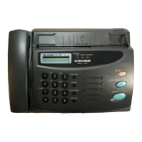
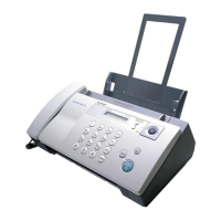
This document describes the SHARP UX-177H facsimile machine, a half-duplex, desktop transceiver designed for use with public switched telephone networks and compatible with ITU-T (CCITT) G3 mode.

Function Description

The UX-177H operates as a facsimile machine, a copier, and a telephone. Its core functions are managed by a control PWB, which integrates a ROCKWELL 1-chip fax engine (SFE-LC), ROM, RAM, and a modem (R96DFXL-CID).

Transmission Operation: When a document is loaded, the document sensor activates, and the pulse motor feeds the document into the machine. Upon pressing the START key in off-hook mode, transmission begins. The CCD scans the document, converting the analog image signal into binary data via an AD converter. This data is then transferred to the RAM's image buffer, encoded, and stored in the transmit buffer. The modem converts this data from parallel to serial, modulates it, and sends it over the telephone line.

Receive Operation: Reception can be initiated manually by pressing the START key in off-hook mode or automatically upon detection of a CI signal by the LIU. The SFE-LC controls the modem to prepare for data reception. Once in phase C, the serial data from the modem is converted to parallel form by the modem interface of the SFE-LC and stored in the RAM's receive buffer. This data is then decoded, reproduced as a binary image, and transferred to the recording processor. The SFE-LC controls the motor rotation and strobe signal to print the image line by line using the thermal head.

Copy Operation: To make a copy, the COPY key is pressed when a document is on the document table and the telephone is on-hook. The document is fed to the scan line, and the image signal from the CCD is converted to binary data via the SFE-LC, similar to transmission. This data is then sent to the image buffer in RAM and subsequently transferred to the recording processor for line-by-line printing by the thermal head. The process repeats for multiple copies.

Modem: The R96DFXL modem supports synchronous 9600 bps, half-duplex operation, with error detection and DTMF reception. It features low power consumption and requires only a single 5V power supply. The modem is housed in a single VLSI device package. It can operate over public switched telephone networks (PSTN) through terminations provided by a data access arrangement (DAA). The modem supports G3 facsimile standards, including V.29, V.27 ter, and V.21 Channel 2, and meets the binary signaling requirements of T.30. It can operate at 9600, 7200, 4800, 2400, and 300 bps, and includes V.27 ter short train sequence option. The modem can also perform HDLC framing according to T.30 at 9600, 7200, 4800, and 2400 bps. It features a programmable DTMF receiver and three programmable tone detectors that operate concurrently with the V.21 channel 2 receiver. The voice mode allows the host computer to efficiently transmit and receive audio and fax modem tones. The modem is available in either a 100-pin plastic quad flat pack (PQFP) or a 64-pin quad in-line package (QUIP). General purpose input/output (GPIO) pins are available for host as-signment in both PQFP and QUIP. The modem's small size, single voltage supply, and low power consumption allow the design of compact system enclosures for use in both desktop and portable applications. MONOFAX is a registered trademark of Rockwell International.

Important Technical Specifications

General:

  • Applicable Telephone Line: Public switched telephone network
  • Compatibility: ITU-T (CCITT) G3 mode
  • Configuration: Half-duplex, desktop transceiver
  • Compression Scheme: Modified Huffman and Sharp special mode
  • Scanning Method: Flat-bed, solid-state CCD
  • Recording System: Thermal recording
  • Display: 7 x 5 dots, 1 line by 16-digit display
  • Reception Modes: FAX/TEL/TEL-FAX/A.M.
  • Modem Speed: 9600 bps with automatic fallback to 7200, 4800, or 2400 bps
  • Transmission Time: Approx. 15 seconds (Sharp special mode)
  • Effective Recording Width: 210 mm, max.
  • Effective Scanning Width: 210 mm
  • Automatic Document Feeder: 20 sheets max.
  • Halftone (Gray Scale): 64 levels
  • Contrast Control: Automatic/Dark selectable
  • Copy Function: Standard
  • Telephone Function: Standard (cannot be used if power fails)
  • Noise Emission: Less than 70 dBA (Measured according to DIN 45635.)
  • Power Requirements: 230 V AC, 50 Hz
  • Operating Temperature: 5 to 35°C
  • Power Consumption: Stand-by: 8 W, Maximum: 120 W
  • Dimensions: Width: 341 mm, Depth: 257 mm, Height: 123 mm
  • Weight: 2.9kg

Resolution:

  • Horizontal: 8 dot/mm
  • Vertical: Standard, Fine/Halftone (7.7 lines/mm), Super fine (15.4 lines/mm)

Input Document Size:

  • Automatic Feeding: Width 148 to 216 mm, Length 128 to 297 mm
  • Manual Feeding: Width 148 to 216 mm, Length 128 to 1000 mm

Paper Thickness & Weight:

  • ADF 20 sheets: Thickness 0.06-0.12 mm, Weight 52-104 g/m²
  • ADF 10 sheets: Thickness 0.06-0.12 mm, Weight 52-104 g/m²
  • Special size: Thickness 0.12-0.20 mm, Weight 52-177 g/m²

Usage Features

Operation Panel:

  • Display: Shows various messages during operation and programming.
  • SPEED DIAL key: Dials a 2-digit Speed Dial number.
  • REDIAL key: Automatically redials the last number dialed.
  • FUNCTION key: Selects various special functions.
  • RECEPTION MODE key: Selects the mode of reception.
  • RESOLUTION key: Adjusts resolution and contrast before sending or copying.
  • VOLUME key: Adjusts speaker volume (when SPEAKER key is pressed) or ringer volume.
  • STOP key: Stops operations before completion.
  • Number keys: Dials numbers, enters numbers and letters for storing.
  • Rapid keys: Dials fax and voice numbers automatically. Rapid key 01 also serves as an access key for Mercury Service.
  • SPEAKER key: Dials a number without picking up the handset.
  • START key: Sends or receives a document.
  • COPY/HELP key: Makes a copy (if document is in feeder) or prints a help list/quick reference guide.

Document Loading:

  • Ensure documents are of suitable size and thickness, free from creases, folds, curls, wet glue, wet ink, clips, staples, and pins.
  • Place documents face down in the hopper, aligning guides to document size.
  • The top edge of documents should be gently placed into the hopper for the feed roller to take the first page for transmission.
  • Curled edges should be straightened.
  • Do not load documents of different sizes or thicknesses together.
  • Double-side coated documents and documents on facsimile recording paper should be inserted manually.

Maintenance Features

Troubleshooting:

  • Communication Errors: Refer to the troubleshooting section for solutions to common problems like incomplete signal frames, inability to recognize DCS/NSS signals, line disconnections, and mode changes.
  • Echo Protection: Soft switch SW-A1 No. 1 is used to protect from echo in reception.
  • Forced 4800 bps Reception: SW-A1 No. 2 can be set to force receptions at 4800 bps, improving success rates and reducing handshake time.
  • Footer Print: SW-A1 No. 3 enables automatic recording of reception date, sender machine number, and page number at the end of reception.
  • Maximum Page Length: SW-A1 No. 4 sets the maximum page length for copy, transmit, and receive operations to prevent paper jams.
  • CSI Transmission: SW-A1 No. 5 controls whether the machine sends its own telephone number (CSI signal) to the remote fax machine.
  • DIS Acknowledgment: SW-A1 No. 6 chooses between acknowledging reception of DIS (NSF) after receiving two DISS (NSFs) or one DIS (two NSFs), useful for overseas communication to avoid echo suppression.
  • Non-modulated Carrier Detection: SW-A1 No. 7 allows sending a non-modulated carrier before the image signal to avoid echo suppression, useful for overseas communication.
  • EOL Detect Timer: SW-A1 No. 8 selects between a 25-second or 13-second timer for End Of Line detection, effective in overriding communication failures with some facsimile models.
  • Modem Speed: SW-A2 No. 1-4 sets the initial modem speed, with a default of 9600 bps. Can be adjusted to a slower speed to reduce fallback time.
  • Sender's Information Transmit: SW-A2 No. 5 controls whether the HEADER PRINT content is output at the receiving machine.
  • H2 Mode: SW-A2 No. 6 determines reception of H2 mode (15 sec transmission mode).
  • Communication Error Treatment: SW-A2 No. 7 determines how communication errors are treated when RTN is sent due to a received image error.
  • CNG Transmission: SW-A2 No. 8 controls CNG transmission in key pad dialing mode.
  • CED Tone-Signal Interval: SW-A3 No. 1-2 adjusts the CED tone signal interval for international communication to avoid echo suppression problems.
  • Signal Transmission Level: SW-A4 No. 1-5 controls the signal transmission level from -0dB to -31dB (factory setting -8dB).
  • Protocol Monitor: SW-A4 No. 6-7 enables printing of protocol information on communication error or for general troubleshooting.
  • Line Monitor: SW-A4 No. 8 displays transmission speed and reception level on the LCD for line tests.
  • Digital Equalization Setting: SW-A5 No. 1-2 sets line equalization based on distance to the central switching station.
  • Error Criterion: SW-A5 No. 7 selects the error criterion for sending back RTN when receiving image data.
  • Anti-junk Fax Check: SW-A5 No. 8 enables the anti-junk fax function.
  • Auto Gain Control (MODEM): SW-A6 No. 1 enables automatic signal gain control if the reception signal level is under -31dBm.

Diagnostic Items:

  • Soft Switch Setting Mode: Changes soft switch settings (SW-A1 to SW-K1).
  • ROM & RAM Check Mode: Executes sum check for ROM and matching test for RAM, printing results and indicating errors with buzzer sounds.
  • Aging Mode: Copies or prints check patterns sheet by sheet (10 sheets at 1 sheet per 5 minutes).
  • Panel Check Mode: Checks proper operation of each key on the operation panel.
  • Check Pattern Mode: Prints two sheets of check patterns to verify print head status (vertical stripes, full black, full white).
  • Signal Send Mode: Sends various FAX signals to the line at specified levels.
  • Memory Clear Mode: Clears backup memory and resets to default settings.
  • CCD Adjust Mode: Adjusts the optical system for copying.
  • All Black Copy: Checks the print head by executing all-dot print until 2m is obtained or trouble occurs.
  • Auto Feeder Mode: Tests the auto feed function by inserting and discharging a document.

Disassembly and Assembly Procedures:

  • Detailed flowcharts and parts lists are provided for disassembling and assembling various units, including the recording paper cover, document guide lower/upper, upper cabinet, head frame, optical system, speaker, drive system, and PWBs.
  • Specific instructions are given for wire treatment to ensure careful and deliberate handling.

Scan Optical System Adjustment:

  • Procedures include disconnecting AC power, removing the upper cabinet and recording paper tray, disconnecting the main PWB from the TEL/LIU PWB, and connecting an oscilloscope to monitor VIN and ΦT signals.
  • Adjustments involve lightly loosening red screws on the CCD PWB and positioning it to obtain the desired waveform, then tightening screws and applying locking material.

Sharp UX-177 Specifications

General IconGeneral
BrandSharp
ModelUX-177
CategoryFax Machine
LanguageEnglish

Related product manuals