[2] Disassembly and assembly procedures
• This chapter mainly describes the disassembly procedures. For the assembly procedures, reverse the disassembly procedures.
• Easy and simple disassembly/assembly procedures of some parts and units are omitted. For disassembly and assembly of such parts and units,
refer to the Parts List.
• The numbers in the illustration, the parts list and the flowchart in a same section are common to each other.
• To assure reliability of the product, the disassembly and the assembly procedures should be performed carefully and deliberately.
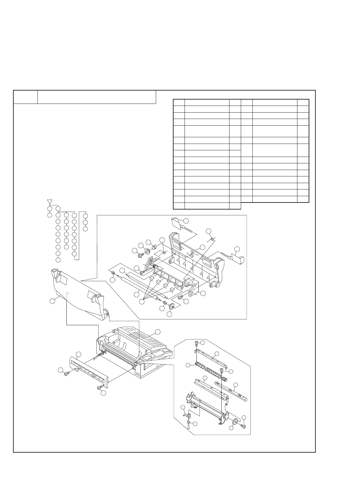
1 Recording paper cover unit
a. Remove the recording paper cover unit, the mechanism unit
according to the flowchart.
Parts list (Fig. 1)
No. Part name Q’ty No. Part name Q’ty
1 Mechanism unit 1 16 Hopper guide, right 1
2 Screw (M3×10) 2 17 Recording paper cover 1
3 Rear cover 1 18 Screw (M3×10) 1
4
Recording paper cover
unit
119
Recording paper guide
upper
1
5 Screw (M3×10) 2 20 Screw (M3×10) 1
6 Platen gear 1
21
Recording paper guide
lower
1
7 Platen bearing 2
8 Platen roller 1 22 Cutter guide 1
9 Anti curl shaft 1 23 Cutter unit 1
10 Anti curl spring 2 24 Screw (M3×10) 1
11 Platen plate 1 25 Cutter gear ass’y 1
12 Screw (M3×6) 1 26 Recording paper sensor 1
13 Pinion gear 1 27 Sensor cable 1
14 Hopper spring 1 28 Paper guide sheet 4
15 Hopper guide, left 1
2
3
4
5
6
7
8
9
10
28
11
18
19
20
21
22
23
24
25
26
27
12
13
14
15
16
17
1
6
12
8
9
10
10
28
11
15
16
17
5
7
5
7
13
14
4
3
2
2
1
18
21
20
19
25
24
22
23
26
27
Fig. 1
UX-177H
3 – 6