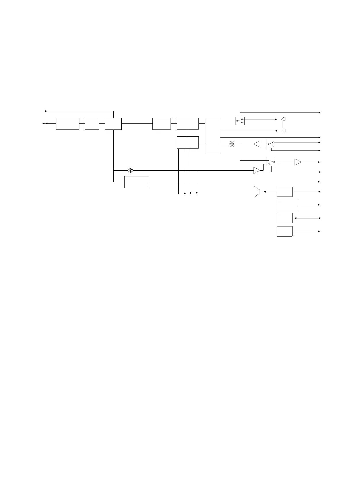
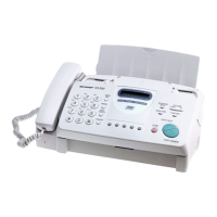
[3] Circuit Description of TEL/LIU PWB
(1) TEL/LIU block operational description
1) Block diagram
2) Circuit description
The TEL/LIU PWB is composed of the following 12 blocks.
1. Line filter block
2. Cl block
3. Polarity guard block
4. Dial control block
5. Pulse transmitting block
6. ON-hook block
7. Hook detection block
8. Communication circuit block
9. Speaker amplifier block
10. Power supply
11. Sensor block
12. Signal selection
3) Block description
1. Line filter block
This block is composed of a (L1) and is used to remove noise
from the telephone line.
2. Cl block
This block is composed of a photo coupler (PC3) and is used to
convert ringer signal into a digital signal.
3. Polarity guard block
This block is composed of diode bridge (REC1) and is used to
supply a current and voltage of the same polarity to the telephone
circuit regardless of reversion of polarity in the telephone circuit.
4. Dial control block
This block is composed of dialer IC (IC105) and crystal oscillator
(×1). The dialer IC is controlled with 4-bit data from operation
panel when the power is switched off. There is not used the dialer
IC, when the power is switched on.
CML
ON-HOOK
BLOCK
MODEM
REC MUTE
TEL MUTE
TEL LINE
SURGE
PROTECTION
BLOCK
DIAL PULSE
GENERATION
BLOCK
HANDSET
RX
LINE
FILTER
BLOCK
POLARITY
GUARD
BLOCK
SPEECH
CIRCUIT
BLOCK
TX
SIG TX
MPX-A
SIGRX
CML
CI
CI DETECTION
CIRCUIT
MODEM
SP
SPEAKER
AMP
SPEAKER
PAPS
DOOR/PAPER
SENSOR
LED
LED
RHS
HOOK
SW
DIAL
CONTROL
BLOCK
POW1
POW4
~
COW1
COW4
~
UX-177H
5 – 8