CHAPTER 2. ADJUSTMENTS
[1] Adjustments
General
Since the following adjustments and settings are provided for this
model, make adjustments and/or setup as necessary.
1. Adjustments
Adjustments of output voltage (FACTORY ONLY)
1. Install the power supply unit in the machine.
2. Set the recording paper and document.
3. When the document is loaded, power is supplied to the output
lines. Confirm that outputs are within the limits below.
Output voltage settings
Output Voltage limits
+5V 4.75V ∼ 5.25V
+24V 23.3V ∼ 24.7V
2. IC protectors
replacement
ICPs (IC Protectors) are installed to protect the motor driver circuit
and the plunger drive circuit. ICPs protect various ICs and electronic
circuits from an overcurrent condition.
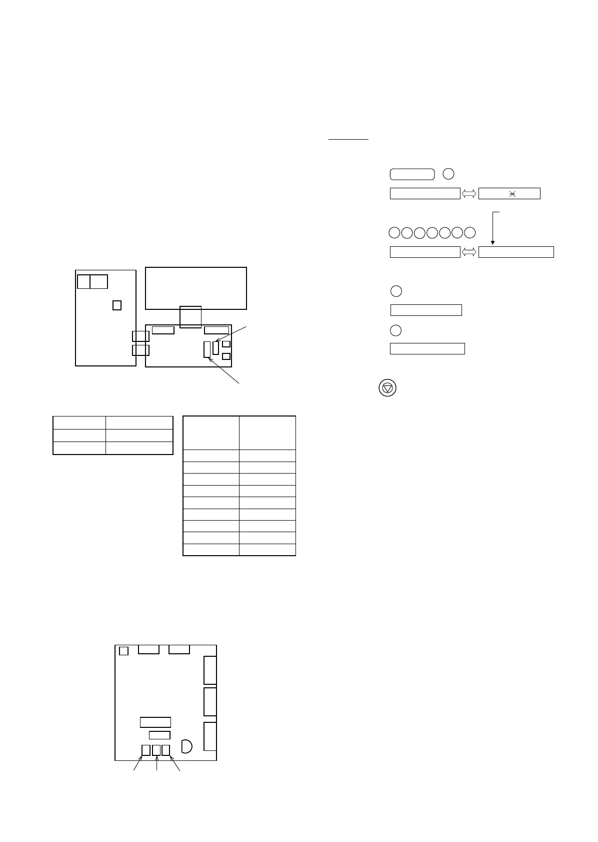
The location of ICPs are shown below:
(1) FU1 (ICP-N20) is installed in order to protect IC’s from an over-
current generated in the motor drive circuit. If FU1 is open, replace
it with a new one.
3. Settings
(1) Dial mode selector
DIAL mode (Soft Switch No. SWB4 DATA No. 3)
POWER
SUPPLY
MJI MJ2
CNSP
CNLIUA
CNLIUB CNLIUB
CNLIUA
CNTH CNPN
CNPW
CNMT
CNLED
CNCSW
CONTROLTEL/LIU
CNCCD
(step 1) Select "OPTION SETTING".
KEY : FUNCTION 4
DISPLAY: OPTION SETTING PRESS OR #
(step 2) Select "DIAL MODE".
KEY:
DISPLAY: DIAL MODE 1=TONE, 2=PULSE
(step 3) Select, using "1" or "2".
KEY: 1
DISPLAY: TONE SELECTED
KEY: 2
DISPLAY: PULSE SELECTED
(step 4) End, using the "STOP" key.
KEY:
Cursor
When initially registering,
the mode shows 1=TONE.
When registering again, the
mode which was registered
formerly is shown.
STOP
#
#
#
# #
# #
Connector
No.
CNPW
Pin No.
1DG
2DG
3 +5V
4 VTH-ON
5MG
6MG
7 +24V
8 VTH
9 VTH
CNPS
CNLIUB
CNLIUA
CNTH
CNPW
CNPN
CNCCD
FU1
CNMT
CNCSW CNLEDCNCUT
UX-177H
2 – 1