XG-C330X/C430X
1 – 5
RS-232C Terminal: 9-pin mini DIN female connector
Pin No. Signal Name I/O Reference
1 Not connected
2 RD Receive Data Input Connected to internal circuit
3 SD Send Data Output Connected to internal circuit
4 Not connected
5 SG Signal Ground Connected to internal circuit
6 Not connected
7 RS Request to Send Connected to CS in internal circuit
8 CS Clear to Send Connected to RS in internal circuit
9 Not connected
RS-232C Terminal: 9-pin D-sub male connector of the DIN-D-sub RS-232C adaptor
Pin No. Signal Name I/O Reference
1 Not connected
2 RD Receive Data Input Connected to internal circuit
3 SD Send Data Output Connected to internal circuit
4 Not connected
5 SG Signal Ground Connected to internal circuit
6 Not connected
7 RS Request to Send Connected to CS in internal circuit
8 CS Clear to Send Connected to RS in internal circuit
9 Not connected
RS-232C Cable recommended connection: 9-pin D-sub female connector
Pin No. Signal Pin No. Signal
1CD 1 CD
2RD 2 RD
3SD 3 SD
4ER 4 ER
5SG 5 SG
6DR 6 DR
7RS 7 RS
8CS 8 CS
9CI 9 CI
Note
• Depending on the controlling device used, it may be necessary to connect Pin 4 and Pin 6 on the controlling
device (e.g. computer).
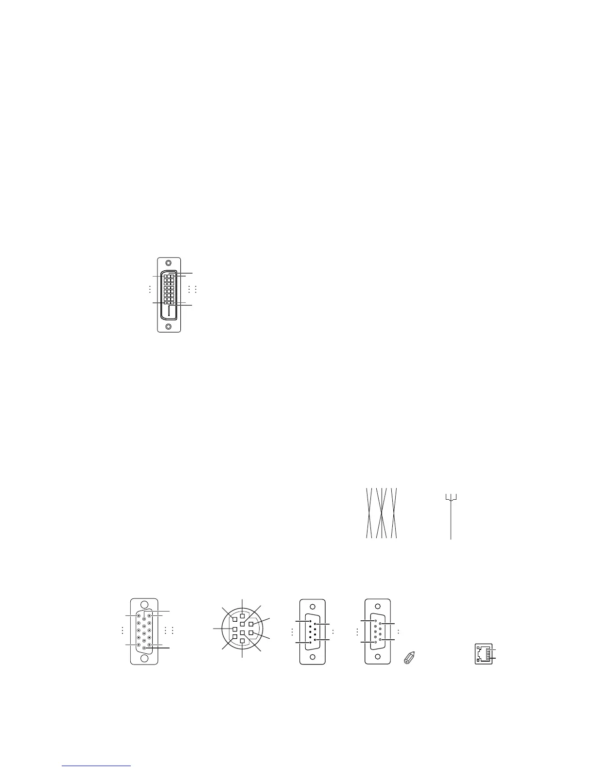
LAN Terminal : 8-pin RJ-45 modular connector
Pin No. Signal Pin No. Signal
1TX+ 5
2TX- 6 RX-
3RX+ 7
48
8
9
6
5
12
4
3
7
1
6
11
5
15
10
COMPUTER-RGB/COMPONENT INPUT 1,
2 and COMPUTER-RGB/COMPONENT OUTPUT Terminals
:
15-pin mini D-sub female connector
COMPUTER-RGB Input/Output
1. Video input (red)
2. Video input (green/sync on green)
3. Video input (blue)
4. Not connected
5. Not connected
6. Earth (red)
7. Earth (green/sync on green)
8. Earth (blue)
9. Not connected
10. GND
11. Not connected
12. Bi-directional data
13. Hor izontal sync signal: TTL level
14. Vertical sync signal: TTL level
15. Data clock
Component Input/Output
1. P
R
(C
R
)
2. Y
3. P
B
(C
B
)
4. Not connected
5. Not connected
6. Earth (P
R
)
7. Earth (Y)
8. Earth (P
B
)
9. Not connected
10. Not connected
11. Not connected
12. Not connected
13. Not connected
14. Not connected
15. Not connected
15
69
51
96
8...1
Projector
Pin No.
4
5
6
Computer
Pin No.
4
5
6
Connecting Pin Assignments
1724
1
9
16
8
Pin No. Signal
1 T.M.D.S. Data 2-
2 T.M.D.S. Data 2+
3 T.M.D.S. Data 2 Shield
4 Not connected
5 Not connected
6 DDC Clock
7 DDC Data
8 Not connected
9 T.M.D.S. Data 1-
10 T.M.D.S. Data 1+
11 T.M.D.S.Data1Shield
12 Not connected
DVI-D Input Terminal
Pin No. Signal
13 Not connected
14 +5 V Power
15 Ground
16 Hot Plug Detect
17 T.M.D.S. Data 0-
18 T.M.D.S. Data 0+
19 T.M.D.S. Data 0 Shield
20 Not connected
21 Not connected
22 T.M.D.S. Clock Shield
23 T.M.D.S. Clock+
24 T.M.D.S. Clock-