12 - POWER STEERING
217
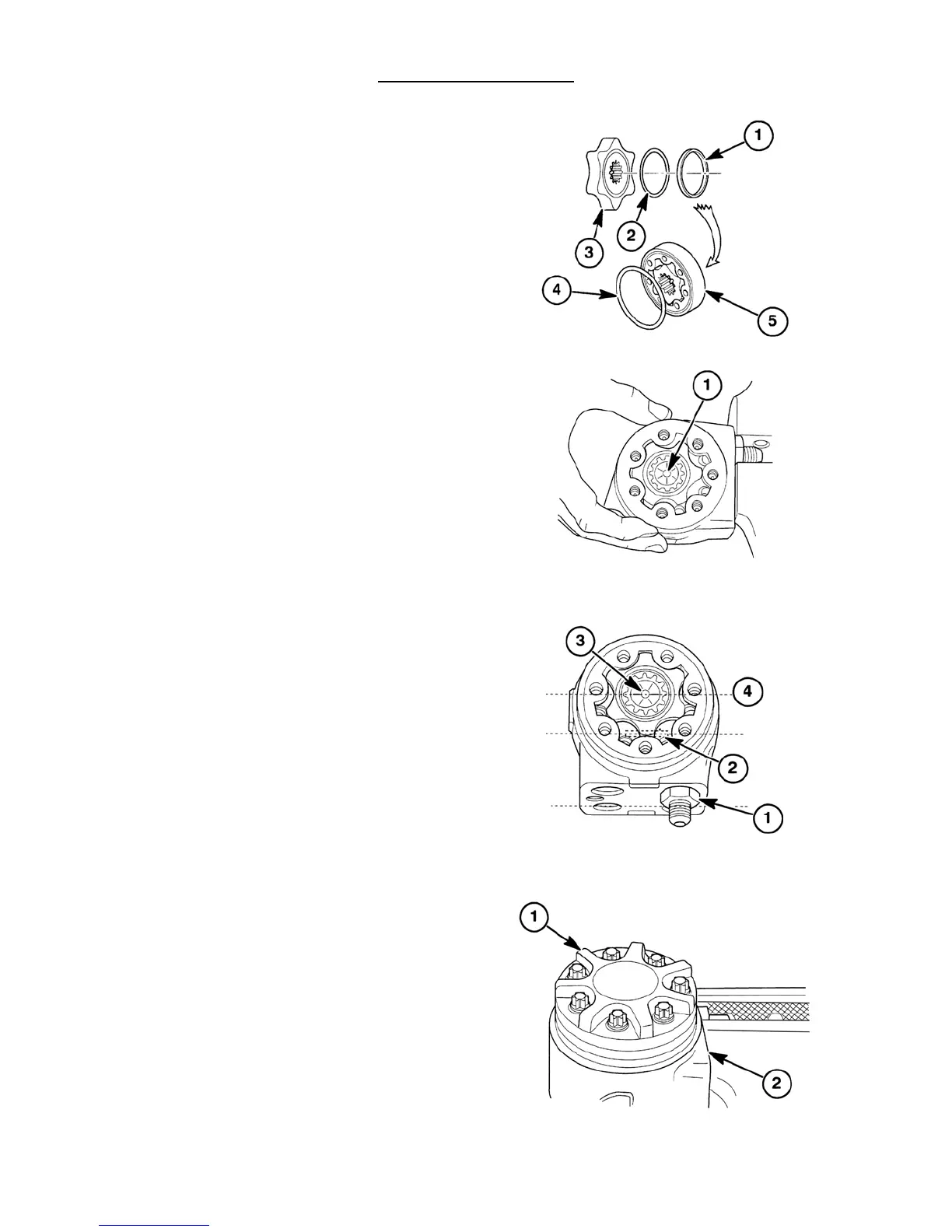
15. Coat a new O-ring, 1, and seal ring, 2, with clean
hydraulic fluid and install them on the rotor.
Install a new O-ring, 4, in the groove on the stator,
5, and then fit the rotor and stator together so that
their O-rings are on opposite sides.
NOTE : The orientation of the rotor and stator on the
drive shaft will determine valve timing in the steering
valve. These parts must be installed exactly as
described for proper operation.
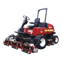
16. Position the rotor and stator on the steering valve
with the rotor seal side up. Visually align the holes
in the spacer plate and stator while doing so.
Before engaging the drive shaft splines with the
rotor, align the mark, 1, on the end of the drive
shaft so that if the line were extended across the
rotor and stator, the line would cut across two of
the valleys of the rotor.
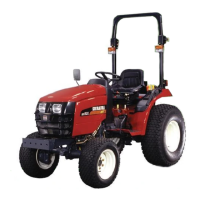
NOTE: When the rotor is positioned correctly, the tip
of one rotor lobe is resting halfway between the valleys,
3, in the stator, directly above the port face side of the
steering valve, 1, and on the opposite side, a lobe is
resting in the bottom of the stator valley.
17. When the steering valve is assembled correctly, the
following areas should be aligned: (a) The port
face, 1, of the steering valve; (b) the pin, 2,
through the spool and sleeve; (c) the line, 3, drawn
on the drive shaft and (d) the middle of the two
valleys, 4, in the rotor. If any of these areas are
not aligned as instructed, the steering valve will
not operate properly.
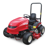
18. Using a new O-ring, position the end cap, 1, on the
steering valve, 2, aligning its bolt holes with those
on the stator. Install the seven end cap retainer
bolts finger tight.
38
39
40
41


 To Next Page