9
3-6. Terminal Arrangement Table
NOTE:
With
thermocouple/voltage/current
input, shorting across B and B
terminal will cause an error.
NOTE:
The optional functions of the
SR90 are subject to the
following conditions:
SR91:
Only one of control output 2,
heater break alarm, analog
output, communication and DI
is selectable.
SR92:
Communication and DI are not
selectable simultaneously.
SR93/SR94:
Communication and analog
output, or communication and
DI are not selectable
simultaneously.
Simultaneous selection of
analog output and DI is
possible, though.
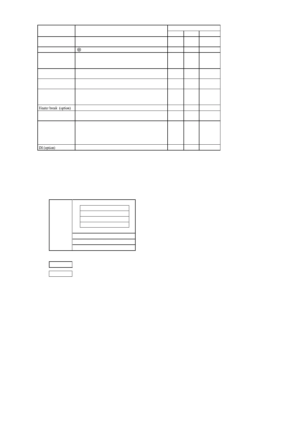
3-7. Insulation Block
The layout of the insulation block is as follows.
In the below table, a circuit which is divided by lines is the circuit which is insulated from other circuits.
Input/heater break
Power
supply
DI
Communication
Analog output
Control output 1
Control output 2
Event output
Reinforced insulation
Functional insulation
Name of terminal Description/Code
Terminal No.
SR91 SR92 SR93 • 94
Power supply
100-240V AC/24V AC: L, 24V DC: +
100-240V AC/24V AC: N, 24V DC:
6
7
8
11-12
11-12
2
4
5
9
10
11
12
11
12
1
11
12
13
14
15
8
9
10
17-18
1-2
4
6
7
11
12
13
14
15
16
2
3
1
19
20
21
11
12
13
5-6
3-4
7
9
10
14
15
16
17
1
2
2
3
1
18
19
20
Protective conductor
Inpu
Control output 1
Control output 2
(option)
R.T.D.: A, thermocouple/voltage/current: +
R.T.D.: B, thermocouple/voltage/current:
R.T.D.: B
Event outpu
(option)
Contact: NO, SSR drive voltage/Voltage/Current: +
Contact: NO, SSR drive voltage/Voltage/Current:
Contact: NO, SSR drive voltage/Voltage/Current: +
Contact: NO, SSR drive voltage/Voltage/Current:
Analog outpu
(option)
Communication
(option)
COM
EV1
EV2
RS-232C: SD, RS-485: +
RS-232C: RD, RS-485:
SG
RS-485: +
RS-485:
+
CT inpu
 Loading...

