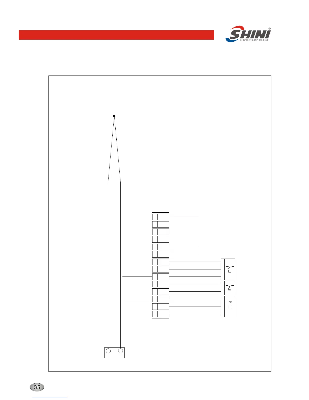
Thermocouple and Terminal Layout
Thermocouple
19
20
K3
-
+
1
2
3
4
5
6
7 8 9
1 2
PE
P
2
1
5
PE
P
S3
S4
Y1
2
P
1
3
5
11
2
PE
4 13
14 15
PE
L1
L2
L3
PE
Valve
Solenoid
Overheat
Protector
Switch
Hydraulic
PE
PE PE
X1
PE
PE
PE
PE
Technical requirements: Connect the positive (+) and negative (-) pole of the thermal couple directly with the
input terminal of the temperature controller, without going through the terminal board.
Connect the pump and heater with the output terminal of overload relay and contactor
directly.
Connect with
contro board
ground wire
Connect door
plate ground
wire
Connect power
supply ground wire
Connect heater
ground wire
Connect pump
ground wire
Structure characteristics and working principle