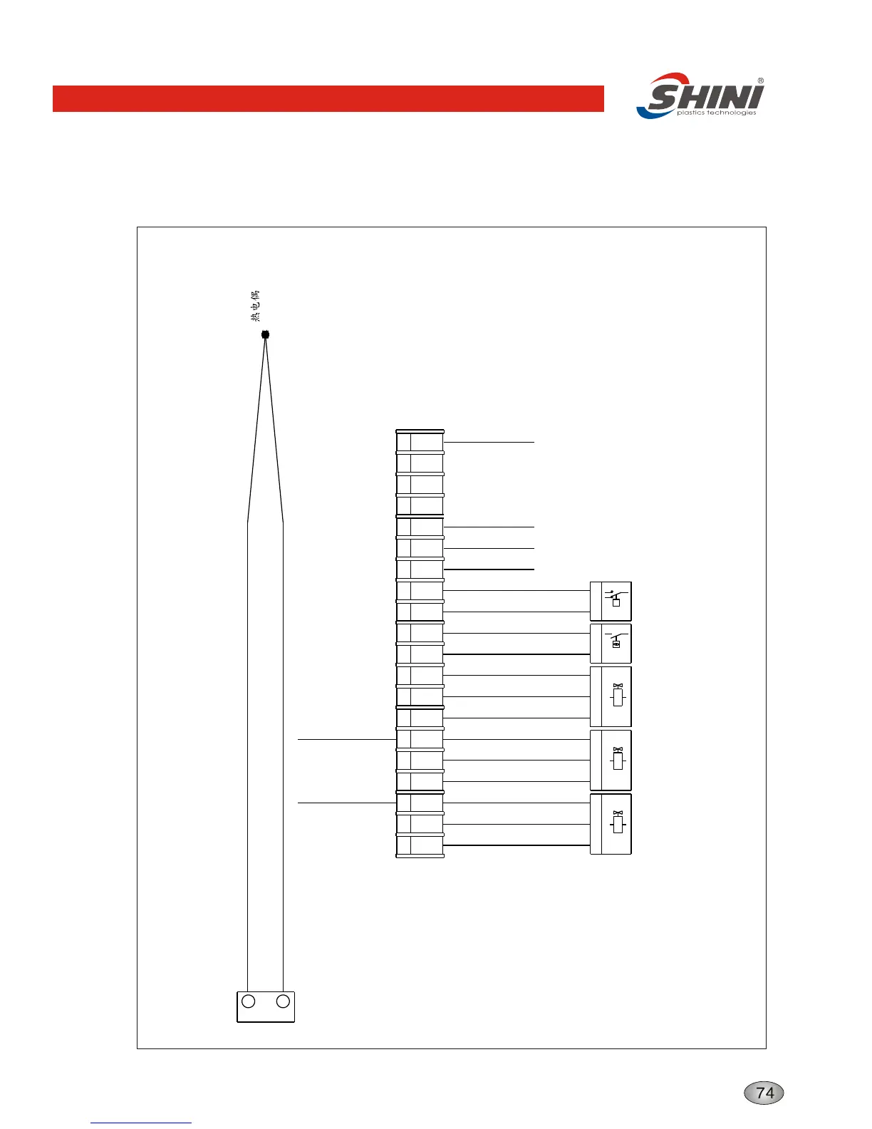
Thermocouple and Terminal Layout
Structure characteristics and working principle
Overheat
Protector
Hydraulic
Switch
Thermocouple
-
+
20
19
K6
2
1 2
2
Y1
1
X1
18
3
PE
PE
PE
21 PE
Y2
2
S3
p
2
C
3
p
S4
51
1
7
3
21
19
L1 L2
L3
PE
21 PE
PE
Y3
4
2
8 9 10 10 11 127654
11
10
PE PEPE
5
PE PE PE PE PE PE PE
Drain
Solenoid
Valve
Turn Into
Solenoid
Valve
Cool
Solenoid
Valve
Technical requirement: 1. Directly introduce positive thermocouple to thermocouple
input end in temperature controller instead
of going through terminal strip.
2. Directly introduce electric heater and pumping
to output end of contactor instead of going
through terminal strip.
Connect with
contro board
ground wire
Connect door
plate ground
wire
Connect power
supply ground wire
Connect heater 2
ground wire
Connect pump
ground wire
Connect heater 1
ground wire