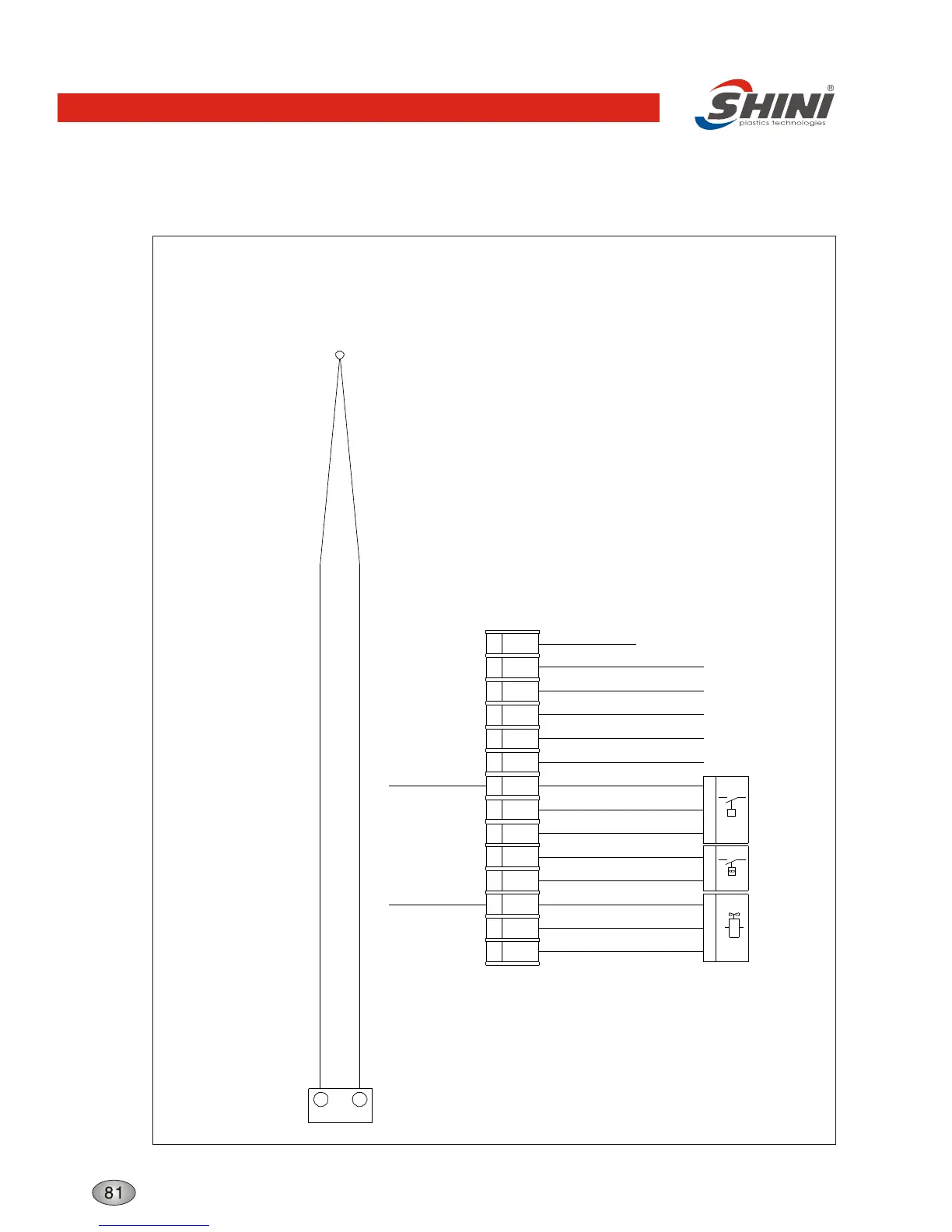
Thermocouple and Terminal Layout
PE
S4
Pressure Switch
1 5
1
5
2
S3
P
P
2
Protector
Overheat
Y1
1 2 PE
5 63 4
15
1 2
2 PE13
X1
Valve
Solenoid
4 16 17 PE
K8
-
+
20
19
PE PE
P
PE
PE
PE
PE
PE
PE
PE
PE
PE
PE
PE
PE
Thermocouple
Connect with
contro board
ground wire
Connect door
plate ground
wire
Connect power
supply ground wire
Connect heater 4 ground wire
Connect pump ground wire
Technical requirements: Connect the positive (+) and negative (-) pole of the thermal couple directly with the
input terminal of the temperature controller, without going through the terminal board.
Connect power wire L1,L2,L3 with input terminal of circuit breaker directly. Connect the
pump and heater with the output terminal of the contactor. Connect all the ground wires
with PE terminal.
Connect heater 3 ground wire
Connect heater 2 ground wire
Connect heater 1 ground wire
Structure characteristics and working principle