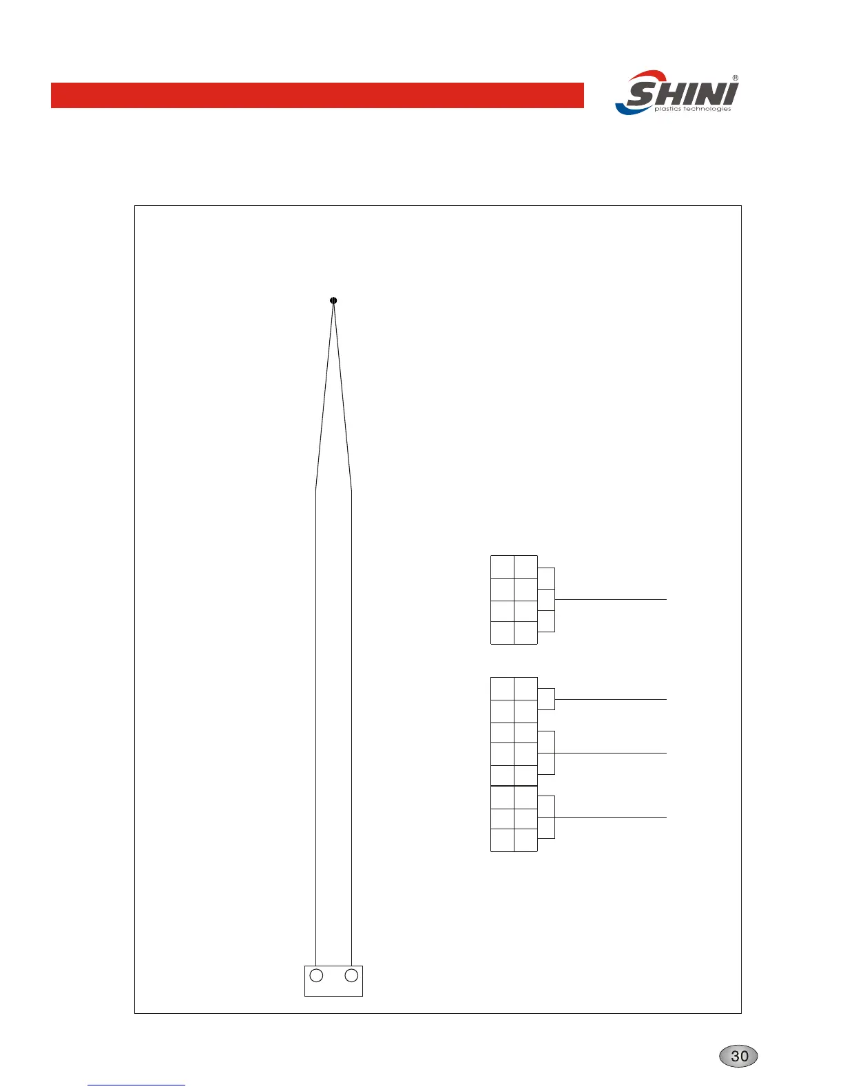
Thermocouple and Terminal Layout
Thermocouple
K3
A-
A+
10
11
+
-
X1
1234
L3 PEL2L142 PE PE11
X2
13 14 15
8 7 6 5 4 3 2 1
Connect Main
Power supply
Connect
Hydraulic
Switch
Connect
Overheat
Protector
Connect
Solenoid Valve
Technical requirement: 1. Directly introduce positive (+) and negative
(-) poles of thermocouple to thermocouple
input end in temperature controller instead
of going through terminal strip.
2. Directly introduce electric heater and pumping
to output end of contactor instead of going
through terminal strip.
Structure characteristics and working principle