- disconnect the Picoflex from the sensor;
- disassemble sensor B, removing it from its seat;
- replace the sensor, assembling it by following the disassembly directions in the reverse order;
- check the sensor reads correctly, as indicated above.
12.2 Distance sensor
Check that the total stroke is 720 notches (maximum permitted error +/- 5 notches along the entire stroke);
If the sensor (A, fig.6) does not read, check:
- connector ribbon cable (C fig.3);
- the correct mounting of the sensor in its housing (Picoflex connector in the direction of the swinging unit);
If the sensor needs to be replaced:
- remove the weight tray
- Disconnect the Picoflex connector;
- unscrew the two self-threading screws (C, fig.6) then remove the sensor from the sensor support (E, Fig. 6);
- mount the new sensor, paying attention to the correct fixing direction of the sensor itself;
- check the functioning in the service environment.
12.3 Replacing zero position sensor (detects rest position of sensor arm)
In the case of an incorrect reading of the distance and diameter values, check the proper operation of the zero sensor as described in chapter
“Service programmes”.
If the sensor (A, fig.6) does not read, check:
- connector ribbon cable (C fig.3);
- the correct mounting of the sensor in its housing (Picoflex connector in the direction of the swinging unit);
If the zero sensor must be replaced, proceed as described in the paragraph “Distance sensor”.
In fact, the zero sensor is mounted on the distance sensor board.
Note:
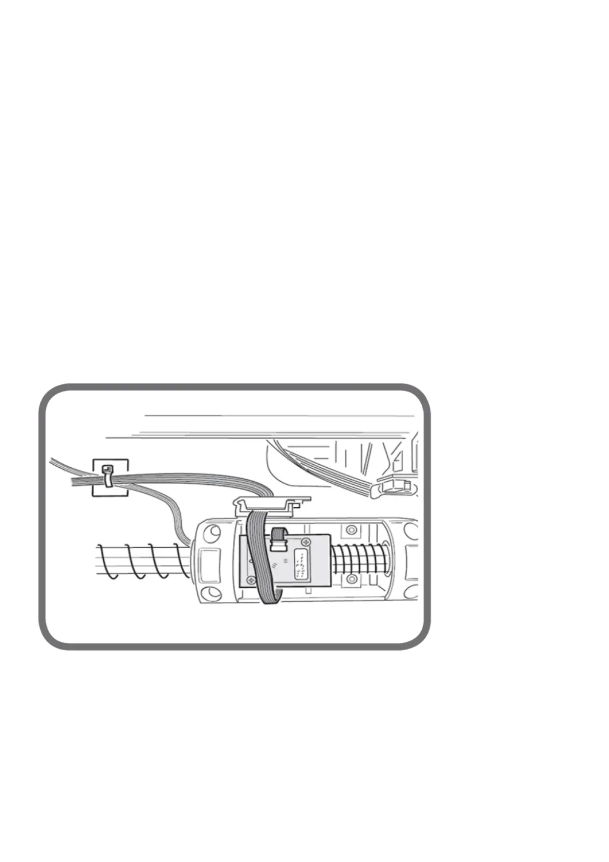
- if the sensor A flat must be replaced, check that the flat is reconnected correctly (see Fig. 8) on the card. Also, the fixing of the flat on the
base must be done so that it is long enough for moving the sensor without having the cable risk to twist around the inside of spring F figure 6.
Fig. 8
12.4 Width potentiometer
Check it is at 5 +/- 1 notches in the rest position. If the resting value obtained is different from this, adjust the potentiometer:
- remove the cap from the sensor mounting box and use a screwdriver to turn the potentiometer shaft until a value of 5 +/-1 appears on the
screen.
If the value visualised does not change, check:
1. the connecting cable (E, fig.3) on connector JSA2;
2. the potentiometer;
3. the Mother card.
If the potentiometer needs to be replaced:
- Unscrew the screws of the external sensor cover in order to remove it;
- disconnect the potentiometer cable;
- unhook the spring from the grommet of the potentiometer support plate;