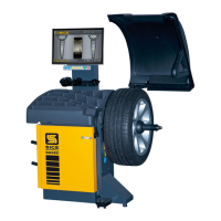
fig. 22
If the laser device does not work, check:
• In the menu dedicated to device activation (see user and maintenance manual);
• The correct wiring of the Laser cable on the ILL board, that is the red wire must be connected to the positive pole (+) and the black wire to
the negative pole (-) see A, Fig.21;
• The correct voltage on the positive pole, approx. +5V DC, whereas on the negative pole 0V DC when on, whereas if off or disabled the voltage
on the positive pole must be approx. +5V DC and approx. 4.5 V DC on the negative pole. To check these voltages use pin P1 on ILL board as the
earth (Fig.21);
• The correct voltage on the connector pins (Fig.20) present on the CPU board and on the ILL board (Fig.21) as indicated in the previous
paragraph;
To carry out the previous voltage checks, the laser device can be enabled using the icon present in the service environment.
• If the result of the above described checks is negative, replace the Laser sensor as follows:
- Remove the transparent cover (D, Fig.22) using the two screws fixing the support;
- Disconnect the two Laser sensor power supply wires;
- Remove the sensor from its seat, then replace the laser with a new one. Reinstall the new sensor by following the removal instructions in
reverse order
WARNING:
Check the correct polarity of the two Laser sensor power supply wires, see figure 21 (red cable +polarity, black cable -polarity).
If it is necessary to replace the laser or if the position of the laser line is NOT correct, perform the adjustment as follows:
• Fix a cord (approx. 600mm) in the hole used for installing the calibration weight on the unit flange;
• Insert a lead on the end of the cord so that the cord remains perpendicular to the ground;
• Enable the laser using the icon present in the service environment;
• Perform the adjustment so that the laser line corresponds with the entire length of the cord. To perform the adjustment adjust:
- Either the light support (A, Fig.22) loosening the two screws fixing the closing panel (B, Fig.22), for lateral line movements;
- Or the laser itself by turning it manually in its seat, loosening the support fixing screws (C, Fig.22).
!
PNEUMATIC SYSTEM DIAGRAM
Air supply: 7-10 bar (100-145 psi)
FIRST"VERSION"OF"PNEUMATIC"SYSTEM"