Check that the CF was inserted correctly in the graphic card and replace the CF if necessary;
• the machine resets.
The fault (usually sporadic) can arise due to the temporary absence of a power supply to the main board, or owing to a disturbance or
malfunctioning of the main board.
Check:
- the correct wiring of the power supply cable of the main board, and the correct insertion of its connectors;
- the proper operation of the “PEAL32F power supply card”, checking in particular the values of the available power supply voltages (power
supply values from 90 Volts to 270 Volts).
If the above checks have not pointed out any faulty components, replace the main board.
The brake at the end of the cycle is too long, or noisy
Check:
- If the bell of the swinging unit or the motor pulley slides on the belt during the braking phase. Then check the tension of the driving belt
(nominal frequency 200Hz tolerance + 5 / -10Hz);
- check the operation of the relay “RL1”, which inverts the current for braking.
If the relay functions correctly at the end of the cycle, you will hear a mechanical tone coming from the Mother board. Otherwise, replace the
PEAL32F power supply card.
The RPA programme does not function correctly, i.e. the wheel is not stopped in a centred position at the end of the spin or when pressing the Start key with
the guard raised (if present)
Check:
- the state of wear and tear of the brake anchor;
- the distance between the anchor of the hub and the brake (nominal distance 0.2 mm -0/+0.05mm).
The spin device is noisy:
Check:
- If the bell of the swinging unit or the motor pulley slides on the belt during initial acceleration. Then check the tension of the driving belt
(nominal frequency 200Hz tolerance + 5 / -10Hz);
• the motor is not mechanically damaged.
- after removing the belt from the spin motor, check for excessive clearance between the pulley and drive shaft.
If the result is positive, check for wear of the pin and seats on the shaft and pulley.
Replace all parts found to be worn.
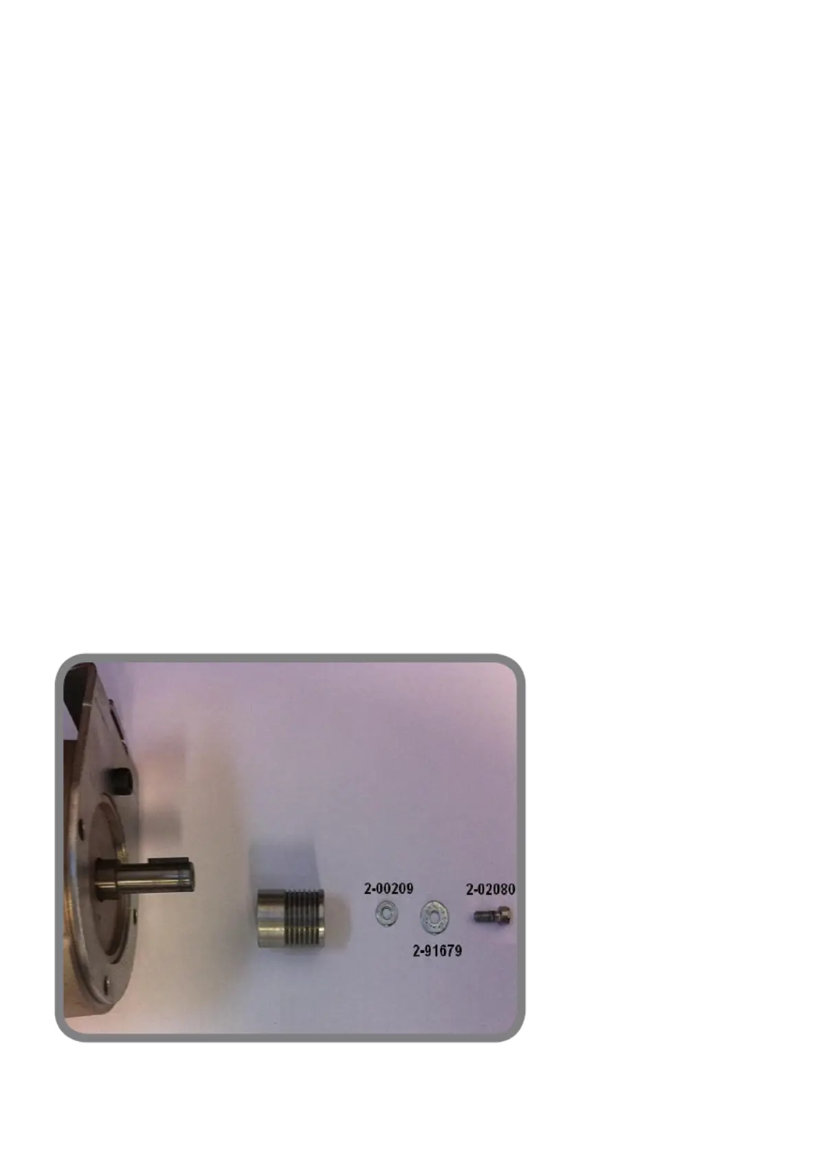
Check that all the parts indicated in fig. 1 are installed correctly:
Code 2-00209 washer 4x9mm thickness 1mm;
Code 2-91679 washer 4X12mm thickness 1mm;
Code 2-02080 M4X10.
Now fasten the pulley in the sequence shown in the figure, applying medium strength Loctite thread lock to the 1 M4X10 screw.
fig. 1
Touching the metal parts of the wheel balancer, you get an electric shock