“RESTART THE MACHINE”
Turn the machine off and then on.
20. LED LIGHT AND LASER LINE DEVICE
If the led light device does not work, check:
• In the menu dedicated to device activation (see user and maintenance manual);
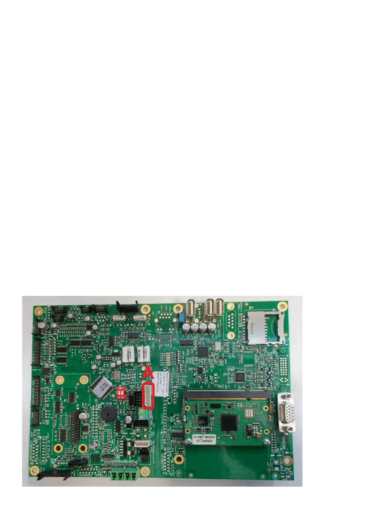
• that the power cable between the ILL board (Fig.21) and the MBUGRF board (A, Fig.19) is installed correctly;
• The correct voltage on the connector pins (Fig.20) on the CPU board:
- P1= board power supply ILL 5V DC;
- P2= led light power supply when enabled for 2-3 V DC (0 VDC if off or deactivated);
- P3= laser power supply when enabled for 2-3 V DC (0 VDC if off or deactivated);
- P4= GND;
- P5= GND;
- P6= Voltage is NOT present (0 V DC) cable inserted correctly, whereas if 3 V DC is present, the cable is not inserted correctly or is
interrupted.
WARNING:
In the latter condition (P6 presence of 3 V DC voltage) the led light and the laser line do NOT work, as the machine automatically recognizes
the device upon switching on, therefore the following icons are NOT present on the video:
• The correct voltage on the connector pins (Fig.21) on the ILL board:
- P1= GND
- P2= laser power supply when enabled for 2-3 V DC (0 VDC if off or deactivated);
- P3= led light power supply when enabled for 2-3 V DC (0 VDC if off or deactivated);
- P4= board power supply ILL 5V DC.
To carry out the previous voltage checks, the led light can be enabled using the icon present in the service environment.
Warning: Pin 1 is the one near to corner B in figure 20.
• If the result of the above described voltage test is negative, check the continuity of the power supply cable;
• Replace the CPU board if necessary;
• If the result of the above described checks is negative, replace the ILL board as follows:
- Remove the light support (A, Fig.22) by unscrewing the screws fixing the closure plate (B, Fig.22);
- Disconnect the cable on the ILL card;
- Remove the transparent cover (D, Fig.22) using the two screws fixing the support;
- Disconnect the two Laser sensor power supply wires;
- Remove the ILL card by turning the screws located at the centre of the card;
- Replace the card with a new one and then reassemble the card, following the removal instructions in reverse order.
WARNING:
Check the correct polarity of the two Laser sensor power supply wires, see figure 21 (red cable +polarity, black cable -polarity).
Fig. 19