- Manually tighten the two screws fixing the washers, recovering all the axial play;
- use an Allen spanner to tighten the two screws with the washers, making four complete turns with the spanner.
- Reconnect the connector of the pick-ups.
- Perform some settling spins;
- perform the sensitivity calibration procedure.
15. REPLACEMENT OF THE COMPLETE SWINGING UNIT
After checking that the unit is the real cause of the machine irregularities, replace it as indicated below.
- Remove the weight tray;
- Disconnect the power supply cable of the motor from the PEAL32F card;
- completely unscrew the 2 screws that hold the pre-load springs (A, fig.10) of the pick-ups;
- unscrew the two M10 dowels that fix the pick-ups (B, Fig. 10);
- disconnect the Picoflex connector of the encoder card then disassemble the card itself;
- remove the belt (D, Fig. 10) as described in the paragraph “Replacement and adjustment of the belt”;
- disassemble the motor support (E, Fig. 10), unscrewing the two M8 fixing screws;
- Remove the swinging unit (F, Fig. 10) after unscrewing the four M12 fixing screws and the relative locknuts;
- Fit the new shaft assembly, tightening the 4 screws to a recommended torque of 72 Nm
- remount the motor support, and then the encoder card on the support itself;
- remount and adjust the 2 pick-ups as described in the paragraph “Replacing and adjusting the pick-up”;
- remount and adjust the belt as described in the paragraph “Replacing and adjusting the belt”;
- Close the weight tray again;
- Perform the unit zero-setting procedure (see paragraph “Zero-setting of the swinging unit”) and the sensitivity calibration procedure.
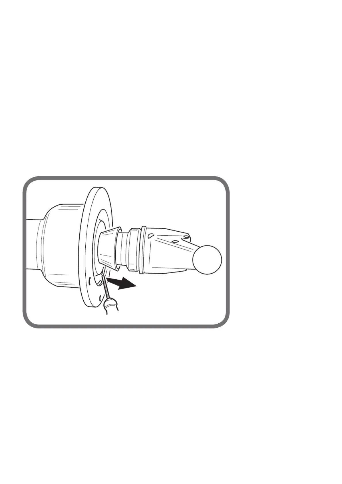
Fig. 11
If it is necessary to disassemble the spring located inside the unit bell, proceed as follows:
- insert a cone on the threaded hub;
- compress the spring by means of the securing ring nut;
- using a screwdriver, remove the ring as shown in figures 11 and 12.