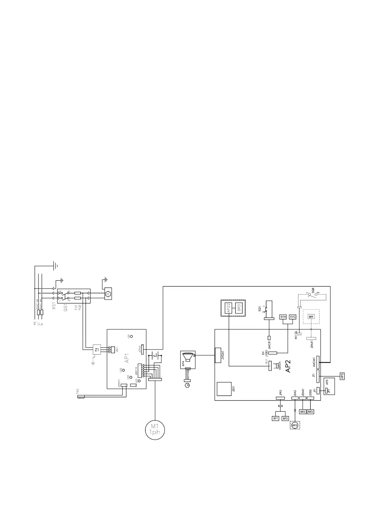
ELECTRICAL SYSTEM GENERAL DIAGRAM
AP1 Power supply unit card
AP2 Mother board (CPU)
AP3 Keypad
AP4 Monitor
AP5 Search card
BP1 Internal pickup
BP2 External pickup
FU1 Fuse
FU2 Fuse
M1 Motor
QS1 Main switch
SQ1 Safety guard micro-switch / start button
SQ8 Micro-switch automatic wheel locking system
RP3 External distance potentiometer
XS1 Power supply socket
YA2 Brake / motor disconnection coil
BR2 Diameter measuring sensor
BR3 Distance measuring sensor
BR5 LASER indicator
BR9 External distance sonar sensor
AP22 LED light
EVA opening solenoid valve
EVC closing solenoid valve!
!
!
!
!
!
!
!
!