it is possible to remove the wheel that may be present on the machine by proceeding as follows:
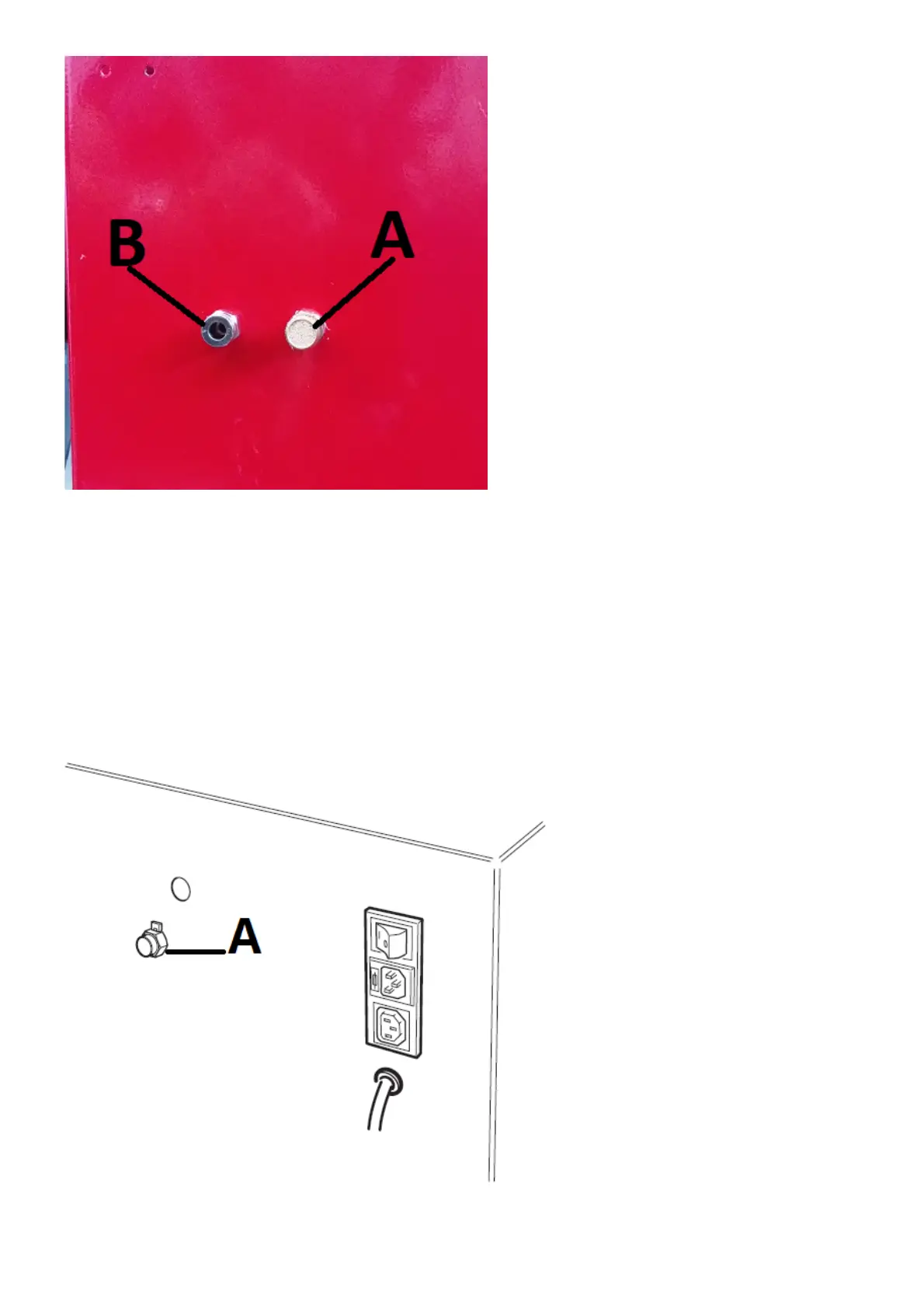
- Close the adjustable drain A by turning clockwise;
- Blow compressed air on the fitting B in the figure;
- restore the correct functioning of the wheel locking device: run 3 complete turns anticlockwise of the previously
closed adjustable outlet A.
In previous machine versions the device can be manually unlocked as follows:
- remove the weight carrier tray;
- disconnect the release circuit line connected to the distributor (A, Fig.17);
- deliver compressed air directly into the connection (pressure must NOT exceed 10 bar).
If the wheel is released after the device has clamped, check for air leaks near the terminal pin (A, Fig.17d). Check as follows:
- open the PL clamping device;
- remove the hub C as follows:
ü on machines with button A (Fig.17b), press button A to expel any air remaining in the clamping system
circuit;
Fig. 17b
ü Insert the special C key included with the machine in the slot on the hub C (Fig. 17c);