3.5 Device layout
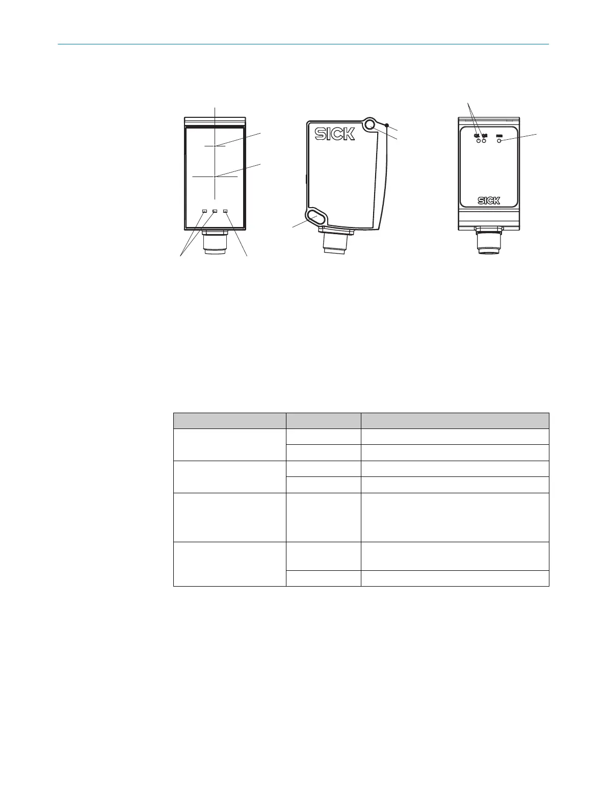
Figure 4: Device layout
1
Optical axis transmitter, laser output aperture corresponds to the front viewing window at
the height of the optical axis.
2
Optical axis, receiver
3
Reference surface (corresponds to distance 0mm)
4
M4 fixing hole
5
Q1/Q2 LEDs (status of digital outputs)
6
Run LED (operational status)
Status LEDs
Status LED Status (color) Description
Q1
O (Orange)
Digital output not active
o (Orange)
Digital output active
Q2
O (Orange)
Digital output not active
o (Orange)
Digital output active
Q1 and Q2 in run mode
ÖÖ (Orange,
Q1 and Q2 alter‐
nately for longer
than 10 seconds)
Error is present. Check general conditions such
as supply voltage, temperature range, EMC dis‐
turbances, etc.
Run
O (Front: Orange)
O (Rear: Green)
Supply voltage is on
o (Orange)
No supply voltage
O = Lights up; Ö = Flashes; o = Does not light up.
3.6 Accessories
Accessories can be found on the product page, which can be accessed via the SICK
Product IDpid.sick.com/{P/N}
{P/N} corresponds to the part number of the product (see type label).
The accessories listed with the relevant product and therefore approved are permitted
to be used in conjunction with the DT35S for safety-related purposes.
A SiLink2 master is specifically required to configure the device.
PRODUCT DESCRIPTION 3
8027663//2022-08-04 | SICK O P E R A T I N G I N S T R U C T I O N S | DT35S
15
Subject to change without notice