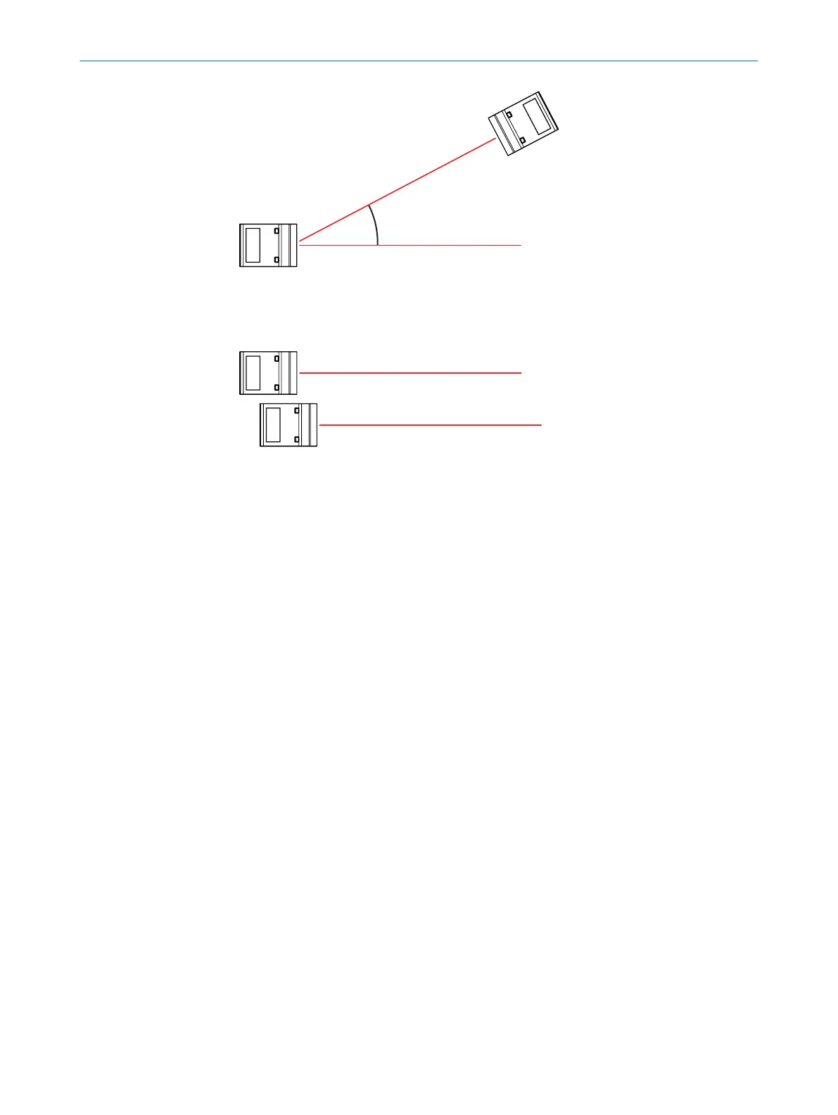
Figure 17: Minimum rotationally symmetrical angle
Installations with devices aligned in parallel will not be affected unless the entire laser
light is redirected into the optical reception area of the other device (direct reflection).
Figure 18: Devices aligned in parallel
5.3
Mounting the device
1. Mount the distance sensor using the fixing holes provided, see "Mechanics/Elec‐
tronics", page 58.
Note the permissible tightening torques of the screws:
°
When using the mounting accessories or equivalent construction: max.
1.2Nm.
°
When using screws with a polyamide spot coating (according to ISO8992):
max. 2.0Nm.
°
For any other type of connection between the device and screws: max.
1.0Nm.
°
The connection between a screw and the housing of the device must be
made using a washer (ISO7092, for size M4) or an equivalent washer.
2. Make the electrical connection. Attach and tighten the tension-free cable, see
"Connecting the device electrically", page 26.
3. Switch on the supply voltage.
✓
The green operating LED lights up.
4. Align the device to suit the application.
MOUNTING 5
8027663//2022-08-04 | SICK O P E R A T I N G I N S T R U C T I O N S | DT35S
25
Subject to change without notice