6 Electrical installation
6.1 Wiring instructions
NOTE
Pre-assembled cables can be found on the product page. which can be accessed via
the SICK Product IDpid.sick.com/{P/N}
{P/N} corresponds to the part number of the product (see type label).
NOTICE
Faults during operation and defects in the device or the system
Incorrect wiring may result in operational faults and defects.
■
Follow the wiring notes precisely.
The electrical connection of the device is configured as an M12 round connector.
The enclosure rating stated in the technical data is achieved only with a screwed plug
connector or protective cap.
All circuits connected to the device must be configured as SELV or PELV circuits. SELV =
safety extra-low voltage, PELV = protective extra-low voltage.
Protect the device with an external 2A slow-blow fuse at the beginning of the supply
cable.
6.2
Connecting the device electrically
1. Ensure the voltage supply is not connected.
2. Connect the device according to the connection diagram, see "Connection dia‐
gram", page 26.
3. Switch on the supply voltage.
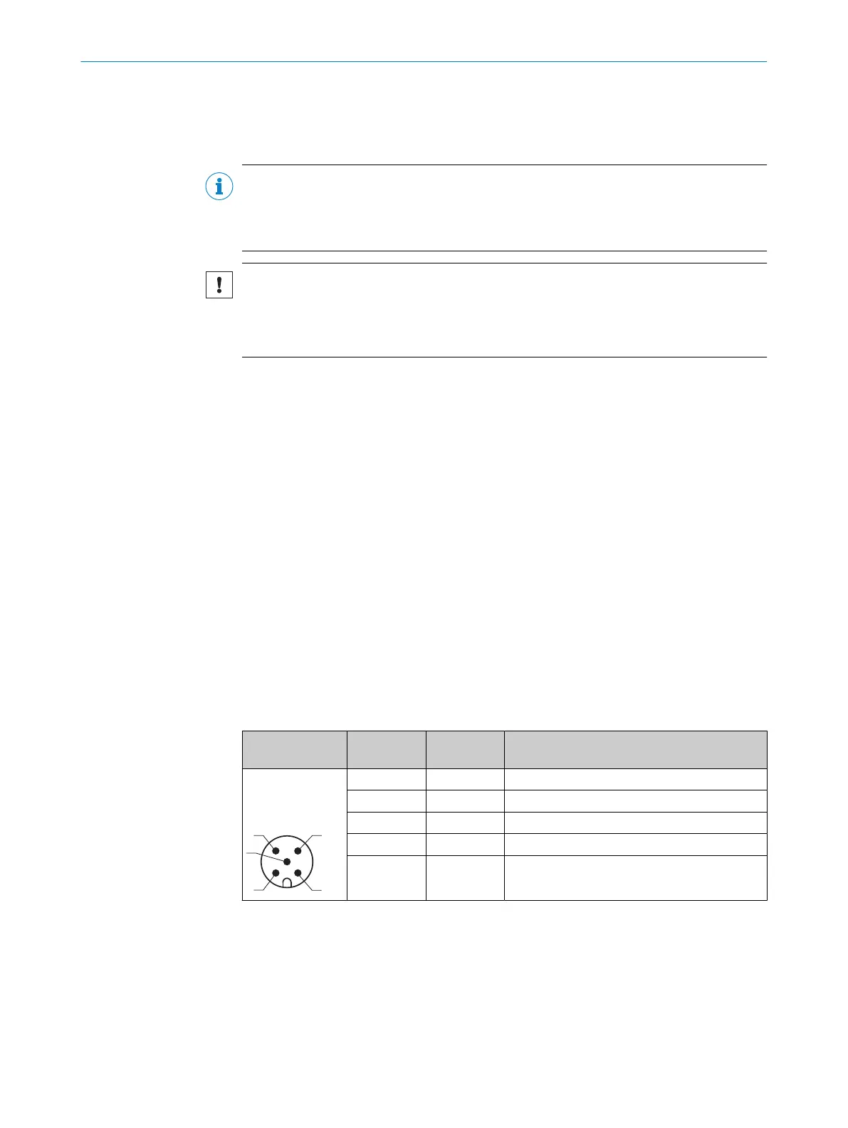
6.3 Connection diagram
Power
Table 1: Pin assignment Power connection
Male/female
connector
Contact Short form Signal description
M12 male con‐
nector, 5-pin A-
coded
1 L+ Supply voltage
2 Qa/Q2 Analog output/ digital output2
3 M Supply voltage: 0 V
4 Q1 Digital output1 / IO-Link
5 MF Multifunctional input MF
6 ELECTRICAL INSTALLATION
26
O P E R A T I N G I N S T R U C T I O N S | DT35S 8027663//2022-08-04 | SICK
Subject to change without notice