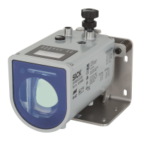
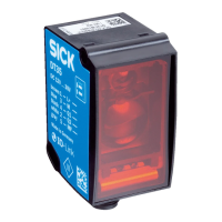
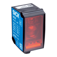
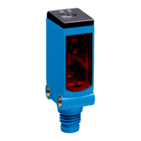
Figure 7: Shield connection in plastic housings
NOTE
Use an appropriate earthing method to prevent equipotential bonding currents flowing
through the cable shield.
5.3 Connecting the sensor electrically
NOTE
The connection diagram and information on inputs and outputs can be found on the
side plate of the sensor.
NOTICE
All electrical circuits must be connected to the device with safety or protective extra-low
voltage (SELV or PELV).
1. Ensure that the power supply is not connected.
2. Connect the sensor according to the connection diagram.
3. Observe the wiring instructions, see "Wiring instructions", page 13.
L+
1
brn
M
3
blu
Q1/C
4
blk
QA/Q2/
¯
Q1/–
2
wht
MF
5
gra
1
Figure 8: Connection diagram, 5-pin plug
1
Multifunctional input
Table 2: Legend for connection diagram
Contact Marking Wire color Description
1 L+ Brown Supply voltage: +10 to 30 V DC
2 Q
A
/Q
2
/Q
1
/- White Output 2: analog output / output signal
switching device 2 / Q
1
not / inactive
3 M Blue Supply voltage: 0 V
ELECTRICAL INSTALLATION 5
8017154/1AVV/2021-03-24 | SICK O P E R A T I N G I N S T R U C T I O N S | DT50-2 Pro
15
Subject to change without notice
 Loading...
