The SICK Flow-X is a gas flow computer designed for measuring and calculating standardized volume flow based on connected devices such as FLOWSIC gas flow meters and process transmitters. It is suitable for a wide range of applications, including natural gas and other fluid measurements, and supports an extensive list of international standard calculations.
Function Description
The Flow-X flow computer serves as a core element in gas measuring systems. It processes data from various sensors and meters to provide accurate flow calculations. The device is available in several configurations:
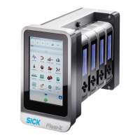
- Flow-X/P: A multi-stream flow computer with an integrated station module and a 7-inch touchscreen, capable of accommodating up to four Flow-X modules.
- Flow-X/C: A compact version of the Flow-X/P, with a Flow-X module integrated into the enclosure. It features three serial and two Ethernet interfaces.
- Flow-X/S: A single module enclosure designed for DIN rail mounting, with direct screw terminals for field connections, used as a single measuring section.
- Flow-X/T: A 7-inch color touchscreen that can be installed in an instrument panel, serving as an operator interface for the Flow-X/S.
The Flow-X modules can operate in single or multi-module configurations. In single-module operation, each module functions as an independent flow computer. In multi-module operation, all modules work together as one flow computer, exchanging data via the Ethernet interface. This multi-module capability allows for fast data exchange between neighboring Flow-X modules, enabling complex system architectures where data from one module (e.g., a gas chromatograph) can be made available to others.
The device supports redundant power supply connections for increased availability, automatically switching to an alternative power supply if the primary one fails.
Important Technical Specifications
The Flow-X flow computer adheres to EU Directives such as EMC Directive 2014/30/EU and Measuring Instrument Directive 2014/32/EU, with CE certification. It also conforms to standards like EN 61000-6-4, EN12405-1, A2, AGA 10, and AGA 8. Type approvals include MID approval (NMI T10548 for Flow-X/P, X/M, X/S, X/R, and T11449 for Flow-X/C).
Operating Temperature and Humidity:
- Flow-X/S: 5 ... 55 °C (41 ... 131 °F), 5... 95% non-condensing
- Flow-X/P and Flow-X/C: -25 ... 55 °C (-13 ... 131 °F), 5... 90% non-condensing
Storage Temperature Range:
- Flow-X/S: -40 ... 75 °C (-40 ... 167 °F)
- Flow-X/P and Flow-X/C: -25 ... 70 °C (-13 ... 158 °F)
Processor: Freescale i.MX processor with math coprocessor and FPGA, 400 MHz.
Memory:
- RAM (Program memory): 2 GB
- Flash (Permanent storage / data recording storage): 1 GB
- MMC (Memory for data recording): 1024 MB
Clock: Real-time clock with internal lithium cell, accuracy better than 1 s/day.
Power Consumption (at 24 V DC, exclusive of external transmitter loops):
- Flow-X/C: Nominal 0.6 A, Peak 1.0 A
- Flow-X/P: Nominal 0.4 A, Peak 0.8 A
- Flow-X: Nominal 0.4 A, Peak 0.8 A
The power supply input circuits are equipped with automatic fuses rated 30 V DC and 1.1 A.
I/O Signal Specifications (Flow-X/M Module):
- Analog inputs: 6 (4 support HART), 4...20 mA, 0...20 mA, 0...5 V, or 1...5 V. High precision (error <0.008% FS, resolution 24 bit), potential-free (optically isolated).
- Temperature inputs: 2 PRT (Pt100), -220 ... +220 °C, resolution 0.02 °C.
- HART modems: 4 loop inputs for HART transmitters.
- Analog outputs: 4, 4...20 mA, 0...20 mA, or 1...5 V. 12 bits A DC, 0.075% FS, update cycle 0.1 s.
- Dual pulse input: 1 high impedance, 0...5 kHz (4x dual pulse) or 0...10 kHz (4x single pulse).
- Digital inputs: 16 high impedance, update cycle 0.5 ms for 2 inputs, 250 ms max for others.
- Digital outputs: 16 open collector, 0.5 A DC, rated 100 V, 24 mA.
- Test output: 1 open collector (two contiguous pulse outputs for test applications).
- Pulse output: 4 open collector, Max. 500 Hz.
- Density/viscosity: 4 periodic time inputs, 100 µs to 5000 µs, resolution < 1ns.
- Inputs of the sphere detector: 4, supports 1, 2, and 4 detector configuration mode, resolution 100 ns (10 MHz).
- Prover bus outputs: 1 meter pulse output for remote flow computers, resolution 100 ns (1 MHz).
- Frequency outputs: 4 for emulation of flow meter signals, max 10 KHz, accuracy 0.1%.
- Serial: 2 RS485/RS-232, 115kb.
- Ethernet: 2 RJ45 Ethernet Interface, TCP/IP, 100 Mbit/s.
Flow Calculation Standards:
- Gas: AGA5, AGA8 Parts 1 and 2, AGA10, AGA-NX19, SGERG-88, GERG-2008, GOST 30319-2, GPA 2172, ISO 6976 (all editions), GSSSD MR113, Wet gas (De Leeuw, Reader Harris).
- Flow: ISO 5167-1, 2, 3 and 4 (all editions), ISO/TR15377, AGA3, AGA7, AGA9, AGA11, V-cone.
- Standard calculations: Recalculation of batch and period totals, weighted averages, calibration curves (linear and polynomial), support for test systems (unidirectional, bidirectional, compact, master counter, double timing, pulse interpolation), and control functions (PID, valve, test, batch).
Usage Features
The Flow-X offers multiple user interfaces for flexible operation:
- Integrated Touchscreen (Flow-X/P and Flow-X/C): A 7-inch touchscreen for direct data access and entry.
- External Touchscreen (Flow-X/T): A separate 7-inch touch panel PC for cabinet installation, compatible with Flow-X/S.
- Flow-X Module LCD Display: Each Flow-X module has a local black and white graphic display for accessing module data and, in Flow-X/P enclosures, station and external module data. It offers similar functions to the main user interface, excluding alphanumeric character entry.
- Flow-X Web Interface: An integrated web server allows external operation via standard web browsers (e.g., Internet Explorer, Firefox, Chrome, Opera). It provides the same features as the main user interface, plus an Explorer Tree for navigation and the ability to download reports and historical data.
User Interface Layout: The touchscreen interface features a main menu with categories like Live Values, Flow rates, Cumulative totals, Flow meter, Temperature, Pressure, Density, Gas properties, Period data, Historical data, Alarms, Event log, Reports, Configuration, and Metrological settings. Navigation buttons include "Main menu," "Up one menu level," "One step backward," "One step forward," "Login" menu, "One page up," "To end of page," "Alarms" menu, and "One page down."
XML Interface: A secured XML interface enables automated communication with a host computer, providing web services for alarm states, device information, menu structure, text translations, event logs, historical data archives, reports, and data value reading/writing.
Configuration Protection:
- Parameter Locking Switch: Each Flow-X module has a mechanical switch to prevent changes to crucial parameters.
- Metrological Seal: Flow-X enclosures can be sealed to protect the parameter locking switch, with one lead seal used for all modules in a Flow-X/P enclosure.
- Passwords: Access to parameters and functions via the touchscreen or a connected computer is password-protected, with different security levels (e.g., Operator, Technician).
Maintenance Features
- Troubleshooting: The manual provides guidance on testing gas flow meter communication, including using FLOWgate™ software for configuration and checking communication status. It also details how to verify analog pressure and temperature transmitter settings and communication.
- Log Files and Reports: After commissioning, it is recommended to delete event logs and reports generated during the process by resetting totals, clearing reports, archives, and the print queue.
- Metrological Settings: The device allows for configuring metrological settings such as Qmin (lowest permissible flow rate) and Qmax (highest permissible flow rate) for the gas flow meter, with corresponding alarms triggered if values fall outside these ranges. These settings are only visible when "MID compliance" is activated.
- Warranty: Opening a module voids all warranty claims, as there are no user-replaceable fuses or components inside.