22
8015675/1EEU/2021-12| SICKO P E R A T I N G I N S T R U C T I O N S | Flow-X
Subject to change without notice
4 INSTALLATION
4.3.4 Electrical connections
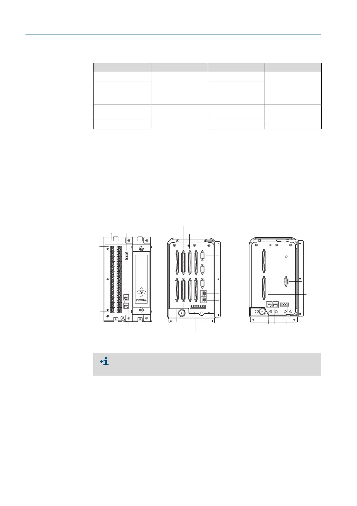
Only the 37-pin D-sub sockets can be used on which a Flow-X module is actually installed.
The three 9-pin D-sub connectors are the serial ports of the display module. These ports
can be used to communicate with devices such as a gas chromatograph or a DCS. COM1
supports RS-232 only at Flow-X/P. COM2 and COM3 can be configured individually for RS-
232 or RS485.
LAN1 and LAN2 are Ethernet connectors for connecting your Flow-X/P or Flow-X/C to your
network. The Flow-XP modules are used in multi-module operation.
Fig. 15: Connection links position
Connection type Flow-X/S Flow-X/P Flow-X/C
RJ45 plug 2x (LAN1 and LAN2) 2x (LAN1 and LAN2) 2x (LAN1 and LAN2)
9-Pin D-sub connector
(serial interface)
-
1x RS-232 COM1(x)
2x RS-232 or RS485
(COM2 and COM3)
1RS-232 COM3 (x) or
1RS-485 COM3
37-Pin D-sub sockets
(I/O and serial ports)
- 8x (X1A - X4A and
X1B to X4B)
2x (X1A and X1B)
Screw terminals 2x (X1A and X1B)
- -
Table 4: Electrical connections
Flow-X/S Flow-X/P
Power 24 V
X1A
X2B
1
39
ETH1 ETH2
X1A
X3A
X2A
X4A
X1B
ETH1
ETH2
Power 24 V
COM 3
COM 2
COM 1
X3B
X2B X4B
X1A
X1B
COM 3
ETH1 ETH2
Power 24 V
Flow-X/C
For more detailed information on the available connections, refer to the Section
“Electrical installation - Connector details” of the Technical Information “Flow-X flow
computer”.