=
+
12 345 678910111213
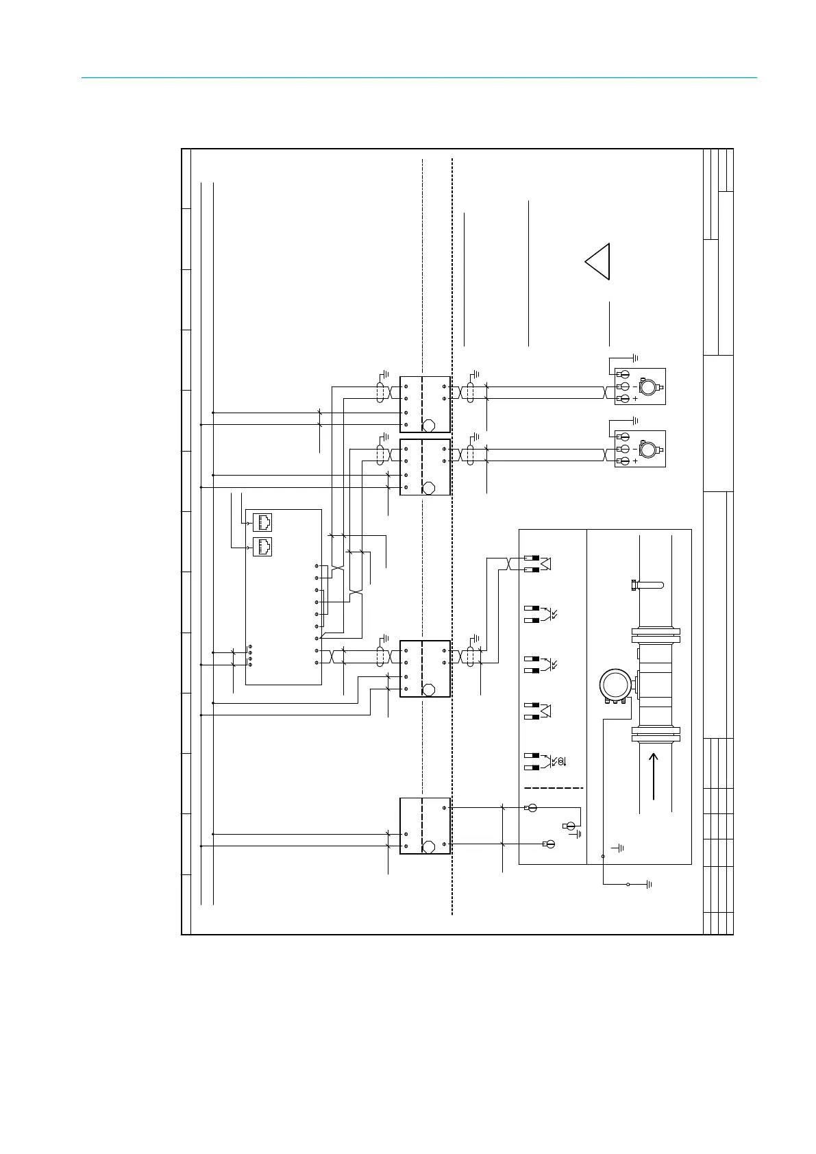
Non Hazard Area
EN 60079-14
24V DC +
24V Gnd
Explosion Hazard Location
Intrinsically-safe installation / Ex i
F. R i ff e r
SICK Engineering GmbH
Bergenerring 27
01458 Ottendorf-Okrilla
Tel.: +(49) 35205 524 10
13.03.2013
Date
created
released
Standard
Date NameRev. ECN
Configuration: Flow-X/P1
Sheet 1
FLOWSIC 600
RS 485
Modbus
31+
32-
33+
34-
51+
52-
41+
42-
81+
82-
1 (+)
2 (-)
.
For further details see
!
WARNING!
Incorrect cabling may cause
operation manual of the
individual device.
RS485 Modbus - approx. impedance 120 Ohm
maximum length: 500 m
EC-Typ-Examination Certificate
For Safety/Entity - Parameters see
Compliance CSA 1298901
Certificate of Conformity
TÜV 01 ATEX 1766 X resp. Certificate of
Flowsic 600 Certificates
National regulation must be observed.
in EU in accordance with EN 60079-14
in North America in accordance with
NEC and CEC, see
Intrinsic safety installation:
Network
SCADA
Ex
safety barrier
Power Supply
24 VDC
+
-
+
-
Intrinsic safety circuits
Non Intrinsic safety circuits
ScreenScreen
Screen ScreenScreen
Screen
2x2x0,5 mm²
Li2YCYv(TP)
2x2x0,5 mm²
Li2YCYv(TP)
2x2x0,5 mm²
Li2YCYv(TP)
2x2x0,5 mm²
Li2YCYv(TP)
2x2x0,5 mm²
Li2YCYv(TP)
2x2x0,5 mm²
Li2YCYv(TP)
2x1,5 mm²
NYY-O
2x1,5 mm²
NYY-O
2x1,5 mm²
NYY-O
2x1,5 mm²
NYY-O
2x1,5 mm²
NYY-O
Control Drawing 781.00.02 (for FL600)
the devices to fail!
Flow computer Flow-X
2x1,5 mm²
NYY-O
Flow-X/P1
X1A
ETH 1 ETH 2
24 VDC
Power supply
0V
0V
+24V
TRx-
TRx+
+AI1
-AI1
+AI2
-AI2
Pressure
Temperature
(internally linked)
5-
6-
1
2
5
9
11
32
33
34
35
2+
1+
ProcessTransmitter
p
Pressure
PE
4...20 mA or HART
loop powered
T
ProcessTransmitter
Temperature
PE
4...20 mA or HART
loop powered
Ex
safety barrier
4...20mA or HART
24VDC
+
-
+
-
+
-
Ex
safety barrier
4...20mA or HART
24VDC
+
-
+
-
+
-
Ex
safety barrier
24VDC
RS485 / 2 wire
TRx+
TRx-
+
-
TRx+
TRx-
Drawing: E_94817