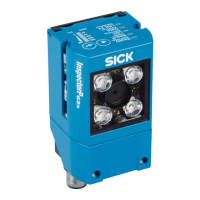
2
“Ethernet” connection (female connector, M12, 4-pin, D-coded)
3
“Power/Serial Data/CAN/I/O” connection (male connector, M12, 17-pin, A-coded)
4
2 sliding nuts, M5; 5.5 mm deep; as an alternative method of mounting the device
5
Viewing window with four LEDs, integrated illumination unit
6
Swivel connector (swivel range 180°)
7
Bar graph display
8
Beeper (under housing cover)
9
5 status LEDs (2 levels)
ß
2 function keys
à
Cover (flap) with two fixing screws (TX6 key, captive)
á
USB port (female connector, type Micro-B, 5-pin)
â
Card slot for microSD memory card
ã
Status LED, status indicator for the microSD memory card
3.3.1.1 Illumination unit
Figure 3: Illumination unit (integrated illumination unit)
1
4 LEDs (color: visible red light, visible blue light; position: 2 on the left, 2 on the right)
2
Feedback LED (color: visible green light)
3
Laser alignment aid (color: visible red light)
NOTE
To avoid being dazzled by the integrated illumination unit, do not look into the viewing
window of the device.
3.3.2 Display and operating elements
Ready
Read Diagn
Result
TeachIn
LED
Auto-Setup
Data
Autofocus
LNK TX
Userdefined
300
200
100
70
40
100
0
[mm]
[%]
O
O
O
O
O
Figure 4: LED status displays, bar graph display and function keys on the top of the device
PRODUCT DESCRIPTION 3
8024439/1EJ6/2022-02 | SICK O P E R A T I N G I N S T R U C T I O N S | InspectorP62x
15
Subject to change without notice

 Loading...