Table 2: Electrical values, teach-in input (ET)
Supply voltage
U
V
10.8 V - 30 V
PNP and
push/pull
NPN
U
V
≥18 V Teach: U > 15 V
Run: U < 5 V
Run: U > 15 V
Teach: U < 5 V
U
V
< 18 V Teach: U > 0.83*U
V
Run: U < 0.28*U
V
Run: U > 0.83*U
V
Teach: U < 0.28*U
V
5.5.2 Wiring the digital outputs
The number of digital outputs available at the connections will vary, depending on the
device, see "Pin assignment of the connections", page 14. If the allocated event occurs
in the read process, then the corresponding digital output is live.
In each case, the digital outputs are short-circuit protected and overcurrent protected.
Switching behavior: PNP or NPN or push/pull
Electrical values
The sum current (100 mA) for all digital outputs is identical.
PNP HIGH: U
V
−3 V; LOW: 0 V
NPN HIGH: U
V
; LOW: ≤ 3 V
Push/pull HIGH: U
V
−3 V; LOW: ≤ 3 V
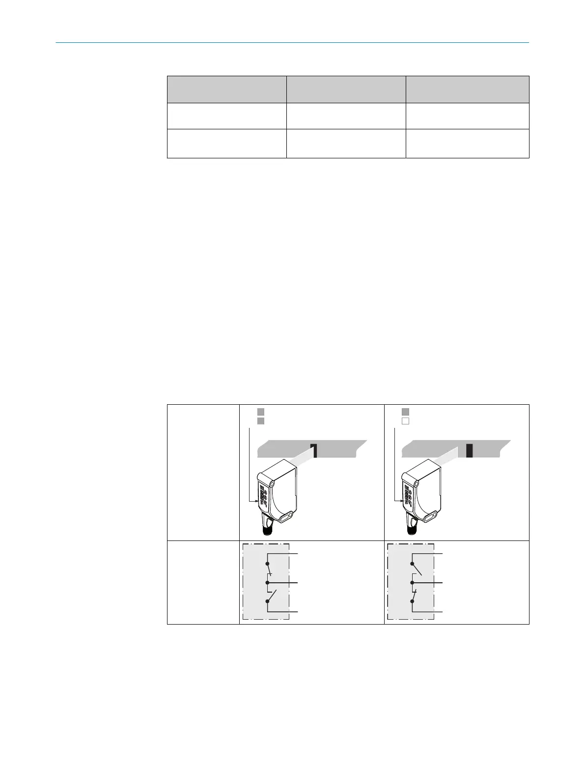
In the case of a push/pull sensor, the signal must be inverted in the control system in
order to obtain the same result as a sensor with NPN switching behavior.
Table 3: Push-Pull
Q
push-pull
(≤ 100 mA)
ELECTRICAL INSTALLATION 5
8026298/2021-08-11 | SICK O P E R A T I N G I N S T R U C T I O N S | KTS Core
15
Subject to change without notice