5.2 Note on the swivel connector
NOTICE
Damage to the connector unit from over-tightening!
The connector unit on the device has two opposite end positions.
■
Do not rotate the connector unit from either of the two end positions by more than
180°.
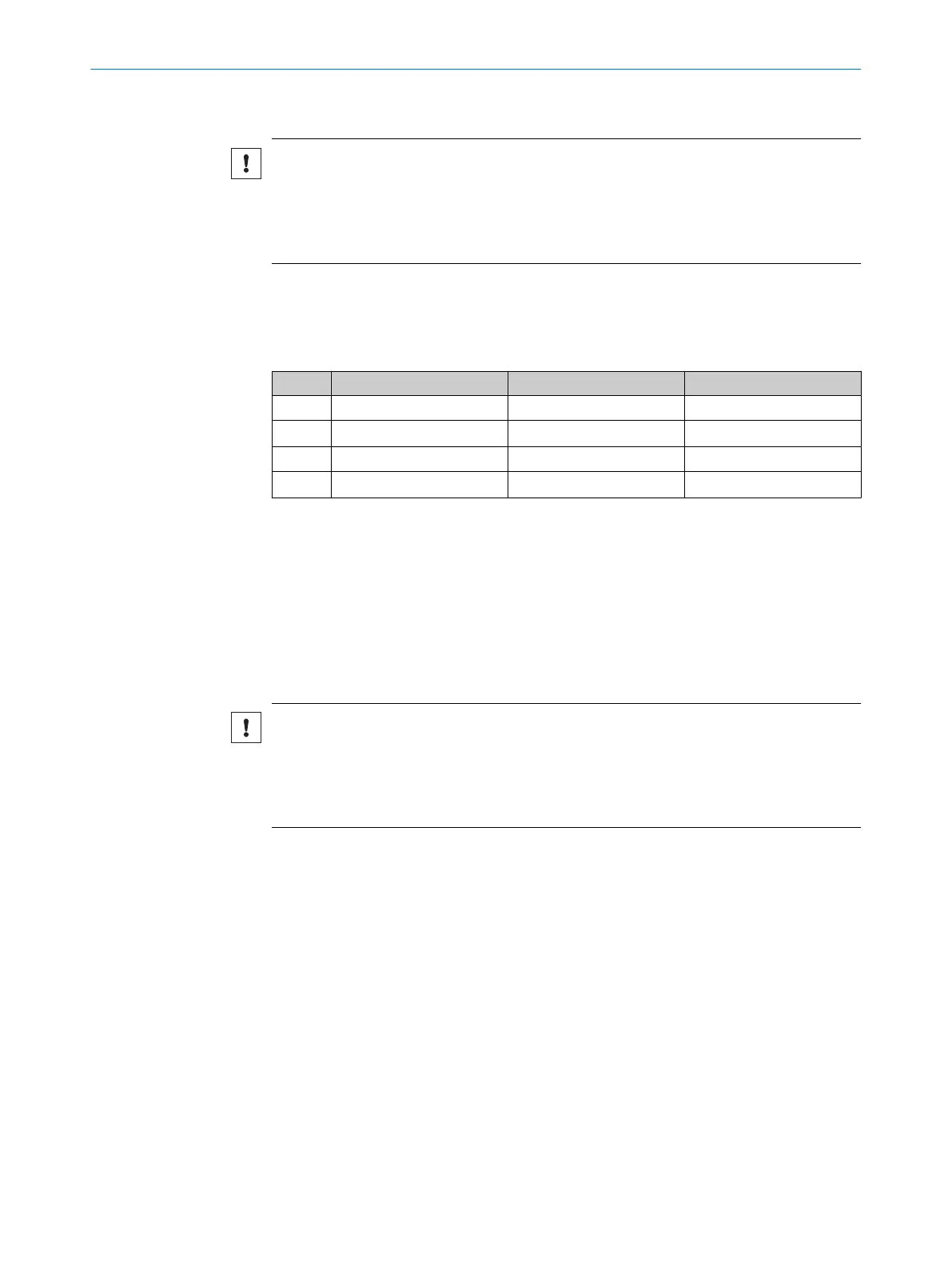
5.3 Pin assignment of the connections
Overview of pin assignment
Table 1: M12 male connector, 4-pin
Push-pull NPN PNP/NPN
1 L+ L+ L+
2 ET ET Q
NPN
3 M M M
4 Q Q Q
PNP
Legend
L+ = Supply voltage
ET = External teach-in
M = Ground
Q = Switching output
5.4
Connecting the supply voltage
NOTICE
Risk of damage to the device!
The device can become damaged if it is connected to a voltage supply that is already
switched on.
•
Only connect the device when the supply cable is de-energized.
The device must be connected to a power supply unit with the following properties:
•
Supply voltage DC 10 V – 30 V (SELV/PELV as per currently valid standards)
•
Electricity source with at least 3 W power
To ensure protection against short-circuits/overload in the customer’s supply cables,
the wire cross-sections used must be appropriately selected and protected.
5.5 Wiring the interfaces
5.5.1 Wiring the digital inputs
The digital inputs can be used to start a teach-in procedure or to select a device
operating mode.
The number of digital inputs available at the connections will vary depending on the
device, see "Pin assignment of the connections", page 14.
Voltage level at the input starts the corresponding function of the device.
5 ELECTRICAL INSTALLATION
14
O P E R A T I N G I N S T R U C T I O N S | KTS Core 8026298/2021-08-11 | SICK
Subject to change without notice