Operating Instructions
LMS1xx Laser Measurement Sensors
Product description
8012471/ZN27/2017-06-09 © SICK AG · Germany · All rights reserved · Subject to change without notice 21
Chapter 3
3.5 Controls and status indicators
3.5.1 User interface
In normal operation the LMS1xx fully automatically without the intervention of an operator.
The interactive configuration is carried out using the provided SOPAS ET configuration
software. The software used for this purpose runs on a PC that is connected to the LMS1xx
via one of the interfaces.
Use the graphic scan view in SOPAS ET to verify the generated measured values and to
verify the measurement area online. During this process, note that the field evaluation
monitor cannot display the data in real-time and therefore does not display all measured
values.
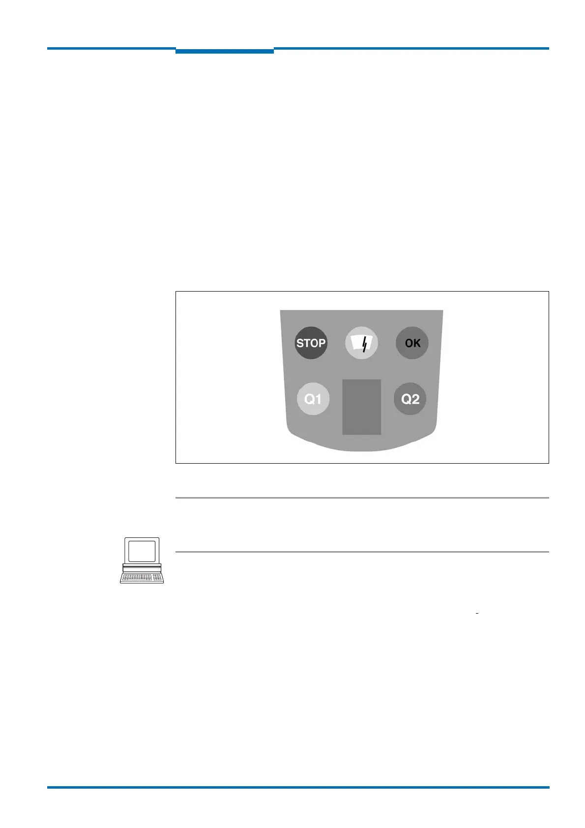
3.5.2 Status indicators
The LEDs and the 7segment display indicate the operational status of the LMS1xx.
Fig. 3: Status indicators
Important On the LMS1xx, along with the standard displays described below, the indication functions
of the LEDs and the 7segment display can be configured in SOPAS ET.
PROJECT TREE, LMS…, PARAMETER, NETWORK/INTERFACES/IOS, DISPLAY.
LMS12x/LMS13x/LMS14x Security and LMC12x/LMC13x VdS (object protection)
You will find further information on the status indicators of these devices in the document
”Technical Information (installer instructions VdS)”, part no.: 8013749, issue in English.
Please see section 1.5 “Further information” on page 9.