Electrical installation
76 © SICK AG · Germany · All rights reserved · Subject to change without notice 8012471/ZN27/2017-06-09
Operating Instructions
LMS1xx Laser Measurement Sensors
Chapter 6
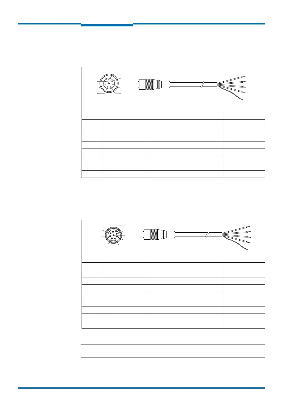
Connecting the „Data“ connection (RS-232) on the LMS11x/LMS15x/LMS182
Adapter cables part no. 6036153 (5 m), part no. 6028420 (10 m), part no. 6036154
(20
m)
Connecting the „I/O“ connection on the LMS11x/LMS13x/LMS15x/LMS182/LMC13x
Adapter cables part no. 6036155 (5 m), part no. 6036156 (10 m), part no. 6036157
(20
m)
Important The OUT1 B, OUT2 B and OUT3 B connections are internally connected to each other.
Pin Signal Function Color of lead
1 RxD HOST Receiver RS232 (Host interface) White
2 TxD HOST Transmitter RS232 (Host interface Brown
3 CAN H CAN bus high Green
4 CAN L CAN bus low Yellow
5 GND RS/CAN Ground RS232/CAN Gray
6 IN1 Switching input 1 Pink
7 IN2 Switching input 2 Blue
8 GND IN 1/IN2 Ground switching input 1 und 2 Red
Tab. 31: Pin assignments and lead color assignments of cables no. 6036153, no. 6028420,
no. 6036154
Pin Signal Function Color of lead
1 INC1 A Input encoder 1, contact A White
2 INC1 B Input encoder 1, contact B Brown
3 GND INC1 Ground encoder 1 Green
4 OUT1 A Switching input 1, contact A Yellow
5 OUT2 A Switching input 2, contact A Gray
6 OUT3 A Switching input 3, contact A Pink
7 OUT1...3 B Switching input 1 .. 3, contacts B Blue
8 OUT1...3 R Switching input 1 .. 3, resistor monitored Red
Tab. 32: Pin assignments and lead color assignments of cables no. 6036155, no. 6036156,
no. 6036157
8-pin M12 female connector,
A-coded (front view)
Illustration may differ
2
1
3
54
6
7
8
...
8-pin M12 male connector,
A-coded (front view)
Illustration may differ
...
2
1
3
5
4
6
7
8