Electrical installation
78 © SICK AG · Germany · All rights reserved · Subject to change without notice 8012471/ZN27/2017-06-09
Operating Instructions
LMS1xx Laser Measurement Sensors
Chapter 6
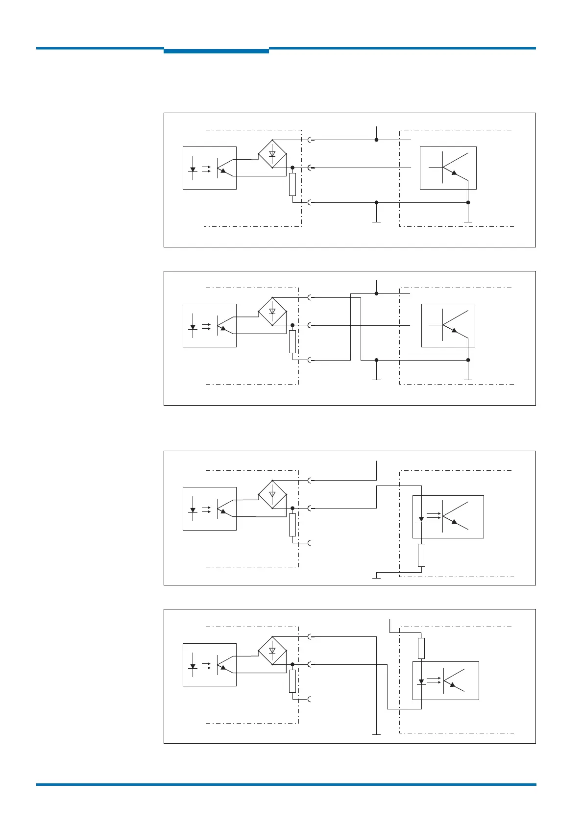
Connection of the switching outputs of the LMS10x/LMS11x/LMS15x to a PLC, non-
floating
Fig. 51: Connection of the switching outputs, e.g. OUT1, to a PLC, non-floating (active high)
Fig. 52: Connection of the switching outputs, e.g. OUT1, to a PLC, non-floating (active low)
Connection of the switching outputs of the LMS10x/LMS11x/LMS15x to a PLC, floating
Fig. 53: Connection of the switching outputs, e.g. OUT1, to a PLC, floating (active high)
Fig. 54: Connection of the switching outputs, e.g. OUT1, to a PLC, floating (active low)
LMS1xx
OUT1 A
OUT1 R
PLC
IN
OUT1 B
DC +24 V
10 K
LMS1xx
OUT1 A
OUT 1 R
IN
OUT1 B
DC +24 V
PLC
10 K
LMS1xx
OUT1 A
OUT1 R
PLC
IN
OUT1 B
DC +24 V
10 K
LMS1xx
PLC
IN
DC +24 V
OUT1 A
OUT1 R
OUT1 B
10 K