°
Group 3: cables that are a source of interference, such as control cables for
inductive loads and motor brakes
°
Group 4: cables that are a powerful source of interference, such as out‐
put cables from frequency inverters, welding system power supplies, power
cables
b
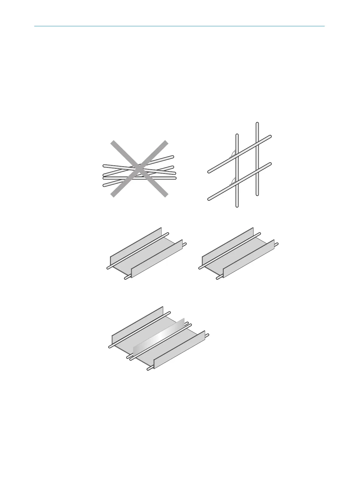
Cables in groups 1, 2 and 3, 4 must be crossed at right angles (see figure 8).
b
Route the cables in groups 1, 2 and 3, 4 in different cable channels or use
metallic separators (see figure 9 and see figure 10). This applies particularly
if cables of devices with a high level of radiated emission, such as frequency
converters, are laid parallel to device cables.
Figure 8: Cross cables at right angles
Figure 9: Ideal laying – Place cables in different cable channels
Figure 10: Alternative laying – Separate cables with metallic separators
6
ELECTRICAL INSTALLATION
26
O P E R A T I N G I N S T R U C T I O N S | TriSpectorP1000 8022395/19OK/2020-12 | SICK
Subject to change without notice