Chapter 5 Operating Instructions
UE402
24 © SICK AG • Industrial Safety Systems • Germany • All rights reserved 8009874/YT67/2016-02-22
Subject to change without notice
Electrical installation
Terminal Assignment
1 24 V DC V DC input (voltage supply)
2 0 V DC V DC input (voltage supply)
3 EFI
B
Device communication to the C4000 receiver
4 EFI
A
Device communication to the C4000 receiver
5 In A1 Input operating mode 1
6 In A2 Input operating mode 2
7 In A3 Input operating mode 3
8 In A4 Input operating mode 4
9 In B1 Input for key-operated pushbutton for bypass or teach-in key-
operated switch
10 In B2 Input for key-operated pushbutton for bypass or run-on
monitoring (SCC)
11 Out B1 Output for In B1
12 Out B2 Output for In B2
13 In A5 Input operating mode 5
14 In A6 Input operating mode 6
15 MCC>BDC Input machine cycle contact, bottom dead centre
16 MCC>TDC Input machine cycle contact, top dead centre
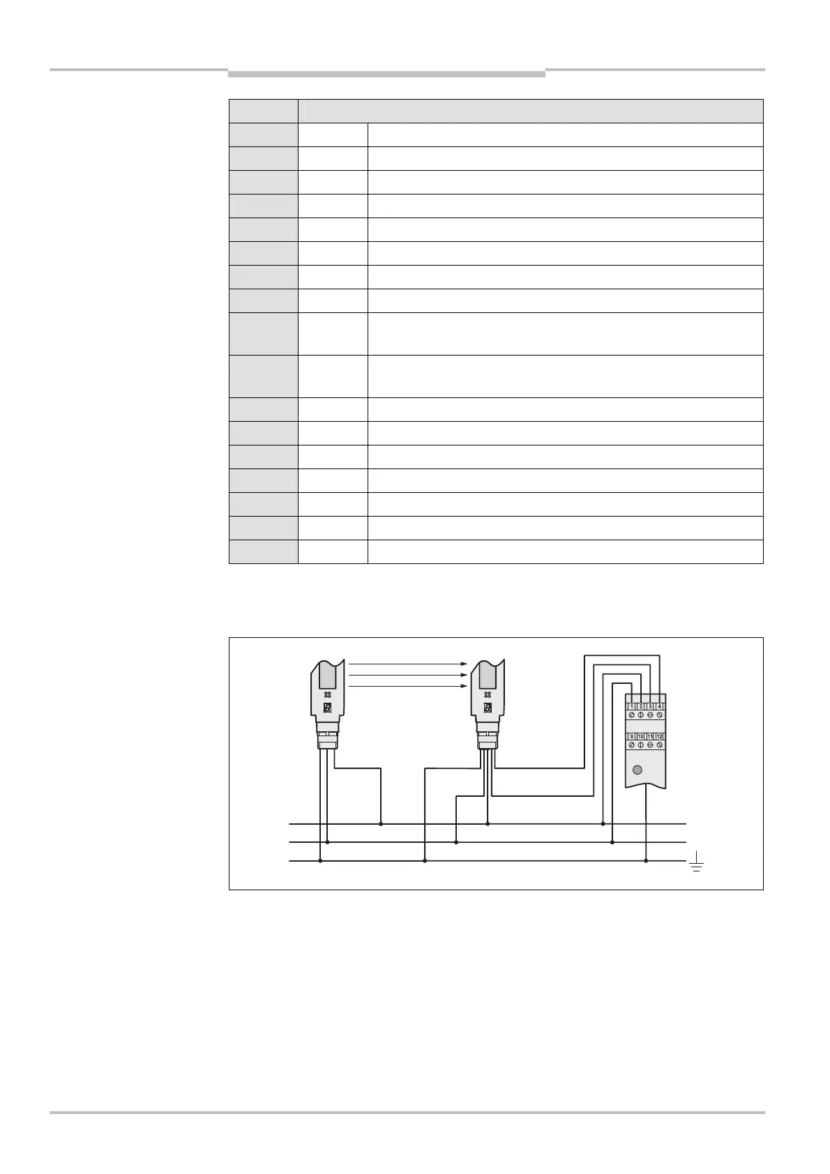
Housing FE Functional earthing
The UE402 also has a functional earth (earth contact to the mounting rail). You must
ensure that the mounting rail is connected to the functional earth (FE) of the safety light
curtain C4000.
of the UE402
Note
connections of the UE402 to
the safety light curtain
C4000