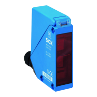
Table 5: AC/DC relay
Relay
3
WT34-R2x0
H
I
max.
= 4A @ 250V AC
4A @ 24V DC
0.125A @ 250V DC
UL: 4A @ 250 V AC, general
use
4A @ 250 V AC, resistive
(NO)
3A @ 250 V AC, resistive
(NC)
4A @ 24 V DC, NO, general
use
3A @ 24 V DC, NC, general
use
R300
B300 (NO contacts only)
D
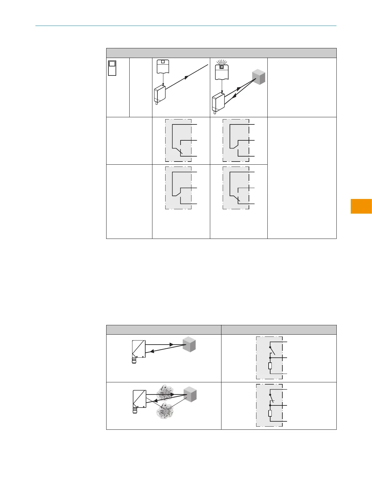
6 Additional functions
Alarm
Alarm output: the sensor (WT34-Vxxx) features a pre-failure notification output (“Alarm”
in connection diagram [see "WT34-Bxxx, WT34-Vxxx", page 27]), which issues a notifi‐
cation if the sensor is only ready for operation to a limited extent. The LED indicator
flashes in this case. Possible causes: sensor is contaminated, sensor is out of align‐
ment. In the good state: LOW (0), if excessively contaminated HIGH (1).
Table 6: Alarm
Alarm (≤ 100mA)
OPERATING INSTRUCTIONS
8009202.1DM8/2022-09-05 | SICK O P E R A T I N G I N S T R U C T I O N S | WT34
29
Subject to change without notice
en