Installation and operating instructions MHS400 smart
05.2017 15
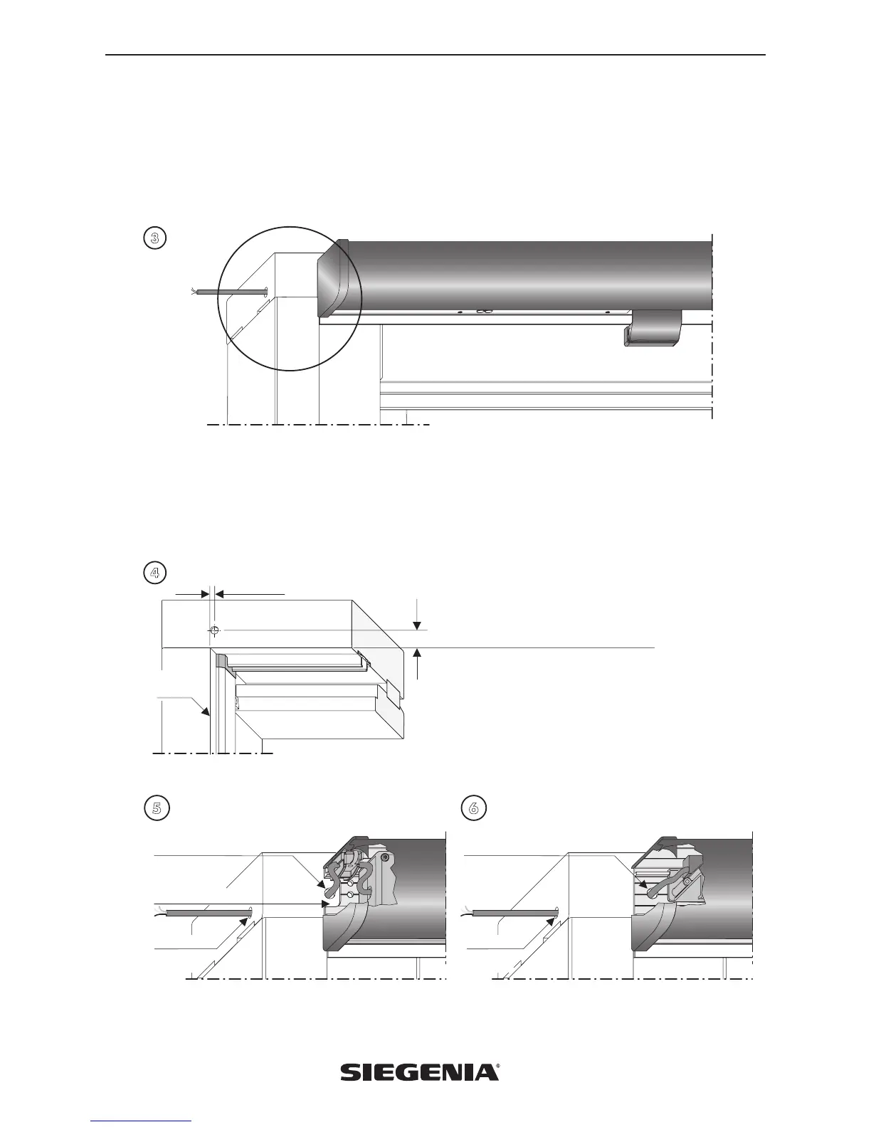
Assembly option 2 – concealed mains cable running
If the customer is responsible for the concealed routing of the mains cable for the slide drive SA and the connection of the
slide drive SA (for scheme A in the power supply, for scheme C in the 5-pin socket), this work must be carried out by a
qualified electrician. When running mains cables for HS elements which have not yet been installed (e.g. new build and
renovation projects), a flexible cable (5 x 1.5 mm
2
incl. connection) for buttons (not included in scope of delivery) must be
provided by the customer and fed concealed through the top section of the HS frame (Fig. 3).
3
Holes for the cable inlet and outlet (each approx. Ø 10 mm) must be made for this purpose, with the centre of each hole
being positioned approx. 7 mm away from the inside frame edge (Fig. 4). All-pole safety isolation is required if the customer
is routing the mains cable. The isolated end of the mains cable must be located inside the power supply housing (scheme A)
or 5-pin socket (scheme C). The connection to the slide drive is made in accordance with the wiring diagrams. In the moun-
ting angle for the slide drive SA, there is a sufficiently dimensioned recess for the cable outlet on the HS frame profile for
scheme A (Fig. 5). The mounting angle for scheme C does not have a recess for the cable outlet (Fig. 6). Concealed mains
cable running to the slide drive SA is through the top edge of the frame on the locking side
5 6
4
Y
7 mm
Inside frame
edge
Bottom edge of HS frame (without cover)
Dimension Y = 15 mm for timber and PVC elements
Dimension Y = central in relation to hollow section in the
case of aluminium elements
Mains cable outlet Ø 10 mm
(drill and deburr)
Recess in
mounting angle
Mains cable-
inlet
Ø 10 mm
Mains cable outlet Ø 10 mm
(drill and deburr)
Mains cable-
inlet
Ø 10 mm
Scheme A Scheme C
 Loading...