16
MHS400 smart Installation and operating instructions
05.2017
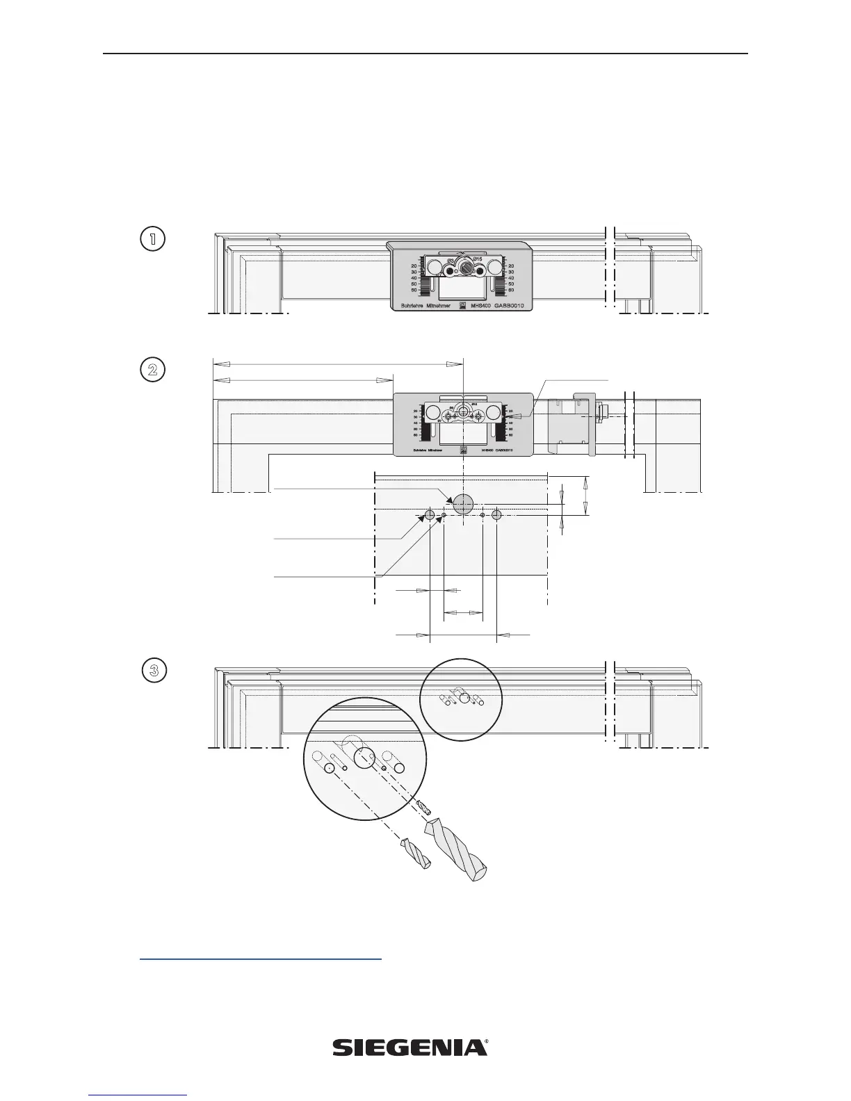
7.3 Drill holes on the lift & slide sash
7.3.1 Positioning and setting the catch jig (accessories)
Place the jig horizontally at the top of the lift & slide sash (Fig. 1), removing existing sash sealings first. Position and set the jig
in accordance with the dimensioning (Fig. 2).
Make the holes for the catch horizontally at the top, noting the drilling diameter (Fig. 3).
1
2
3
300
(416)
X
10,5
29
-0,2
50
8
Positioning and drilling dimensions for the drilled holes for the catch on
the lift & slide sash (Fig. timber profile DIN left - DIN right mirror image)
Adjustment dimension X
Cable feed-through
Ø 15
Supporting peg
Catch base Ø 7
Screw holes Ø 3
Hole Ø 3
for fixing screws
of the catch
Hole Ø 7
for supporting peg of the
catch base
Hole Ø 15
for cable feed-through
Attention: In order for the catch to be positioned correctly on the lift & slide sash, the correct set dimension X (Fig. 2) must
be used. The correct set dimension X for each HS profile system is listed in the installation steps for MHS400 smart on our
download portal:
downloads.siegenia.com/de/00007/index.html
 Loading...