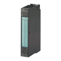
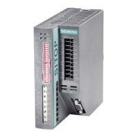
Digital input module DI 8x24VDC HS (6ES7131‑6BF00‑0DA0)
Manual, 03/2015, A5E35243810-AA
5
Preface ...................................................................................................................................................... 4
1 Documentation guide ................................................................................................................................. 7
1.1 ET 200SP Documentation Guide .............................................................................................. 7
2 Product overview ..................................................................................................................................... 10
2.1 Properties ................................................................................................................................ 10
3 Operating mode DI .................................................................................................................................. 13
3.1 Wiring up ................................................................................................................................. 13
3.1.1 Wiring and block diagrams ..................................................................................................... 13
3.2 Parameters/address space ..................................................................................................... 16
3.2.1 High-speed inputs ................................................................................................................... 16
3.2.2 Parameters ............................................................................................................................. 16
3.2.3 Explanation of parameters ...................................................................................................... 19
3.2.4 Address space ........................................................................................................................ 22
3.3 Interrupts/diagnostics alarms .................................................................................................. 23
3.3.1 Status and error display .......................................................................................................... 23
3.3.2 Interrupts ................................................................................................................................. 26
3.3.3 Diagnostics alarms .................................................................................................................. 27
4 Counting operating mode (CNT) .............................................................................................................. 28
4.1 Connecting .............................................................................................................................. 28
4.1.1 Wiring and block diagrams ..................................................................................................... 28
4.2 Parameters/address space ..................................................................................................... 31
4.2.1 Counting .................................................................................................................................. 31
4.2.2 Parameters ............................................................................................................................. 33
4.2.3 Explanation of parameters ...................................................................................................... 35
4.2.4 Address space ........................................................................................................................ 39
4.2.4.1 Assignment of the control interface ........................................................................................ 39
4.2.4.2 Assignment of the feedback interface..................................................................................... 41
4.3 Interrupts/diagnostic messages .............................................................................................. 44
4.3.1 Status and error display .......................................................................................................... 44
4.3.2 Interrupts ................................................................................................................................. 47
4.3.3 Diagnostics alarms .................................................................................................................. 47
 Loading...