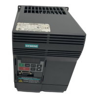
Danger of fire through overheating caused by insufficient ventilation and installation Clearances
Insufficient ventilation and installation clearances result in overheating with danger to persons as a
result of smoke and fire.
Always mount the Power Module in a vertical position
Maintain the following clearances between the components when mounting (*):
Frame size FSA: 30 mm (1.18 inches)
Frame size FSB: 40 mm (1.57 inches)
Frame size FSC: 50 mm (1.96 inches)
Maintain the following ventilation clearances above and below the component:
Frame size FSB: 100 mm (3.93 inches)
Frame size FSC: 125 mm (4.92 inches)
Frame sizes FSD and FSE: 300 mm (11.81 inches)
Frame size FSF: 350 mm (13.77 inches)
Maintain the following ventilation clearances in front of the component:
Frame sizes FSB to FSF: 30 mm (1.18 inches)
Ensure that the cooling air flow of the Power Modules can flow unrestricted.
(*)The Power Modules can be mounted side by side without base components up to an ambient
temperature of 40° C.
In combination with base components and at ambient temperatures of 40° C to 55° C, the specified lateral
minimum clearances must be observed. Where combinations of different frame sizes are concerned, the
longer of the two clearances shall apply.

 Loading...


