Dimension drawings
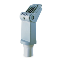
12.8 Stainless steel flanged horn antenna with extension
SITRANS LR250 with mA/HART
Operating Instructions, 10/2019, A5E32220602-AG
197
Flanged horn with extension dimensions
Nominal horn
size,
mm (inch)
Height to sensor reference point
,
, mm (inch)
a)
Measurement range,
m (ft)
Stainless steel flange:
raised or flat-face
20 (65.6)
a)
Height from bottom of horn to sensor reference point as shown: See also Raised-Face
flange (Page 221) or Flat-Face Flange. (Page 226)
b)
-3dB in the direction of the polarization axis (see Polarization reference point (Page 32) for
an illustration).
c)
Optional alloy N06022/2.4602 (Hastelloy
®
C-22 or equivalent). See Raised-Face flange
(Page 221).
Note
Heights to sensor reference point are for stainless steel flanges. For optional alloy
N06022/2.4602 (Hastelloy
©
C-22 or equivalent) see Flanged Horn dimensions above.
 Loading...