EasyManua.ls Logo

Siemens 7ML5431 - Page 201

Siemens 7ML5431
282 pages
Print Icon
To Next Page IconTo Next Page
To Previous Page IconTo Previous Page
Loading...
Dimension drawings
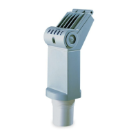
12.10 PTFE Flanged encapsulated antenna (3"/DN80/80A sizes and larger)
SITRANS LR250 with mA/HART
Operating Instructions, 10/2019, A5E32220602-AG
201
Flanged encapsulated antenna (3"/DN80/80A and larger) dimensions
Flange size
mm (inch)
mm (inch)
mm (inch)
mm (inch)
1)
3"/DN80/80A
328 (12.91)
288 (11.34)
343 (13.50)
15 (0.59)
4"/DN100/100A
328 (12.91)
288 (11.34)
343 (13.50)
13 (0.51)
6"/DN150/150A
333 (13.11)
293 (11.54)
348 (13.70)
15 (0.59)
1)
Height from tip of lens to sensor reference point as shown. See also Raised-Face Flange per EN
1092-1.
Flange size
Flange class
Flange O.D.
[mm (inch)]
Antenna
aperture size
[mm (inch)]
Beam angle
(°)
1)
Measurement
range
[m (ft)]
3"
150 LB
190 (7.48)
75 (2.95) 9.6 20 (65.6)
DN80 PN10/16 200 (7.87)
80A
10K
185 (7.28)
4"
150 LB
230 (9.06)
75 (2.95) 9.6 20 (65.6)
DN100
PN10/16
220 (8.66)
100A
10K
210 (8.27)
6"
150 LB
280 (11.02)
75 (2.95) 9.6 20 (65.6)
DN150
PN10/16
285 (11.22)
150A
10K
280 (11.02)
1)
-3 dB in the direction of the polarization axis.
See Raised-Face Flange per EN 1092-1 (Page 224), and Polarization reference point
(Page 32).

Table of Contents

Other manuals for Siemens 7ML5431

Related product manuals