7SR45 Description of Operation
© 2017 Siemens Protection Devices Limited Chapter 1 Page 9 of 34
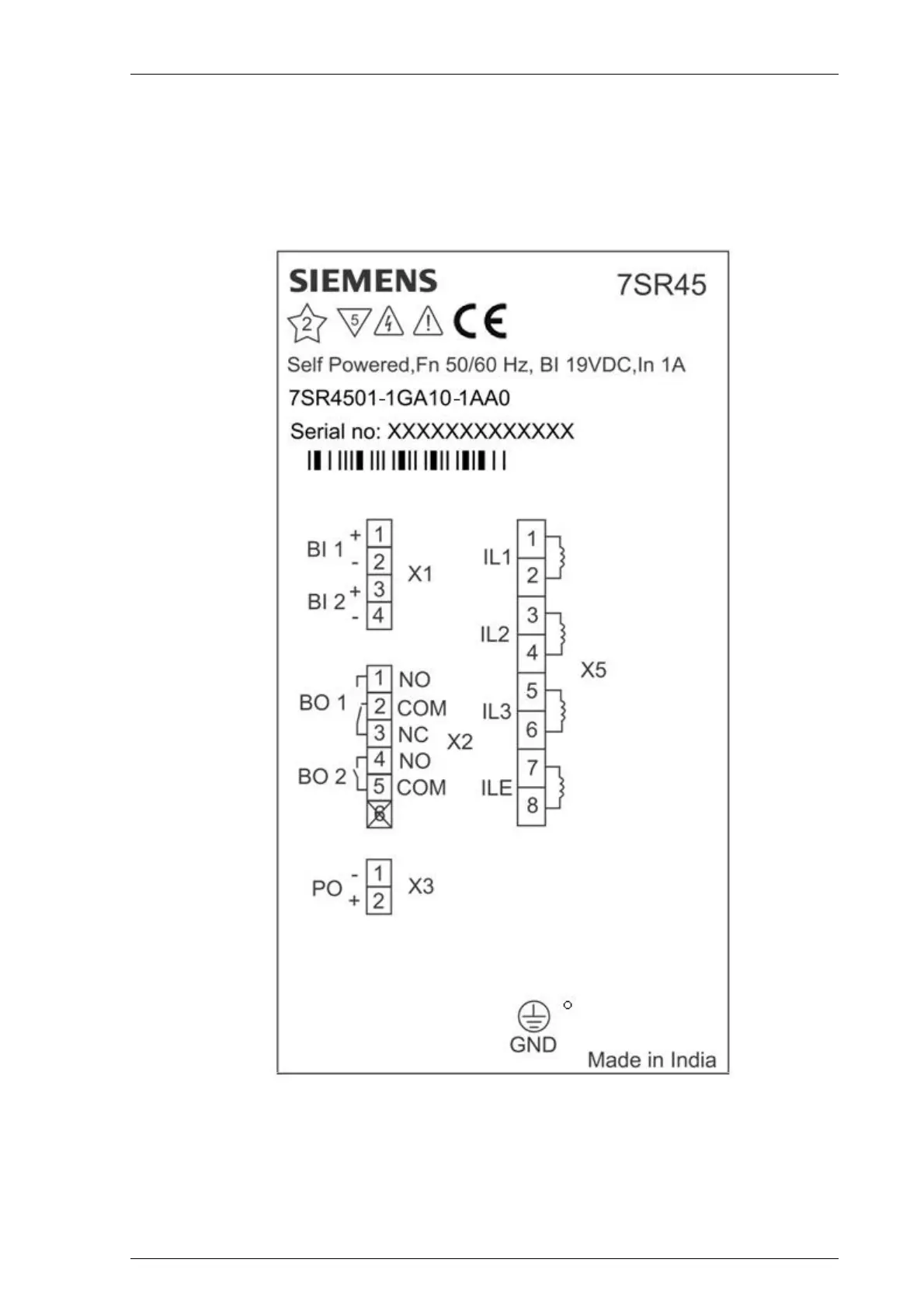
1.6 Terminal Diagram
The relay is housed in a non draw-out case 4U high size 4 case. The rear connection comprises of user-friendly
pluggable type terminals for Binary Input (BI), Binary Output (BO), Impulse output (PO), and Current Transformer
(CT) wire connections.
The CT terminals are suitable for ring type lug connection and to provide a secure and reliable termination.
Figure 1-2 Terminal Diagram of 7SR45 Self Powered Overcurrent and Earth Fault Relay

 Loading...


