7SR45 Description of Operation
© 2017 Siemens Protection Devices Limited Chapter 1 Page 23 of 34
Table 3-7 50LC/SOTF
Parameters Description Default Value Min Max Step Change
50LC/SOTF Setting Current Set point 2 1xIn 20xIn 1
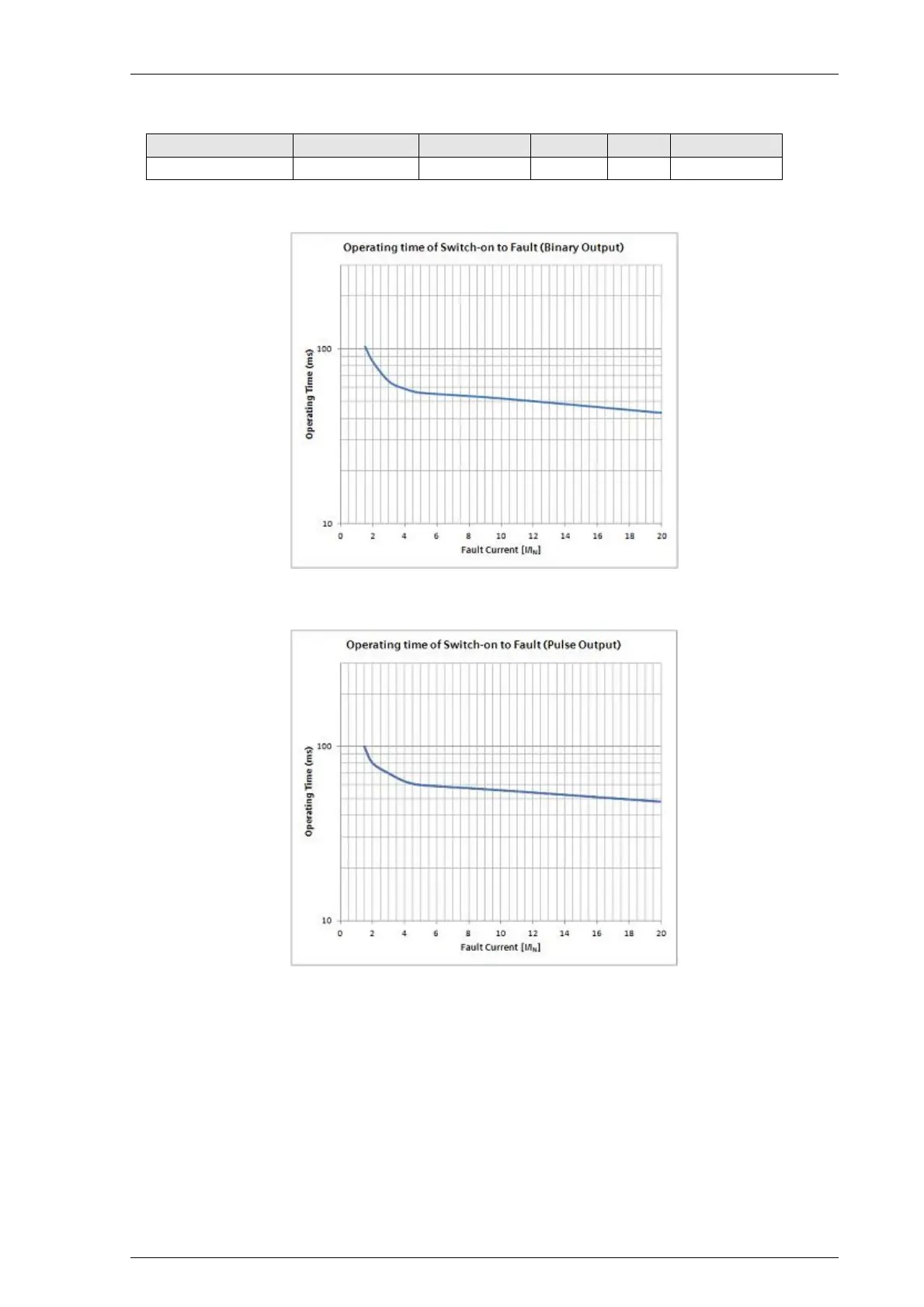
The following graphs show the SOTF operating time.
Figure 3-8 Operating Time for Single Phase Fault with Binary Output
Figure 3-9 Operating Time for Single Phase Fault with Impulse Output
NOTE:
The multi-phase faults results to a shorter operating time.
In the event of the battery going low or drained, the boot up time is increased by maximum of 25 ms.

 Loading...


