Installation
132/214 Revision 11 • INSTALLATION AND OPERATING INSTRUCTIONS • 8DA10 • 861-9601.9
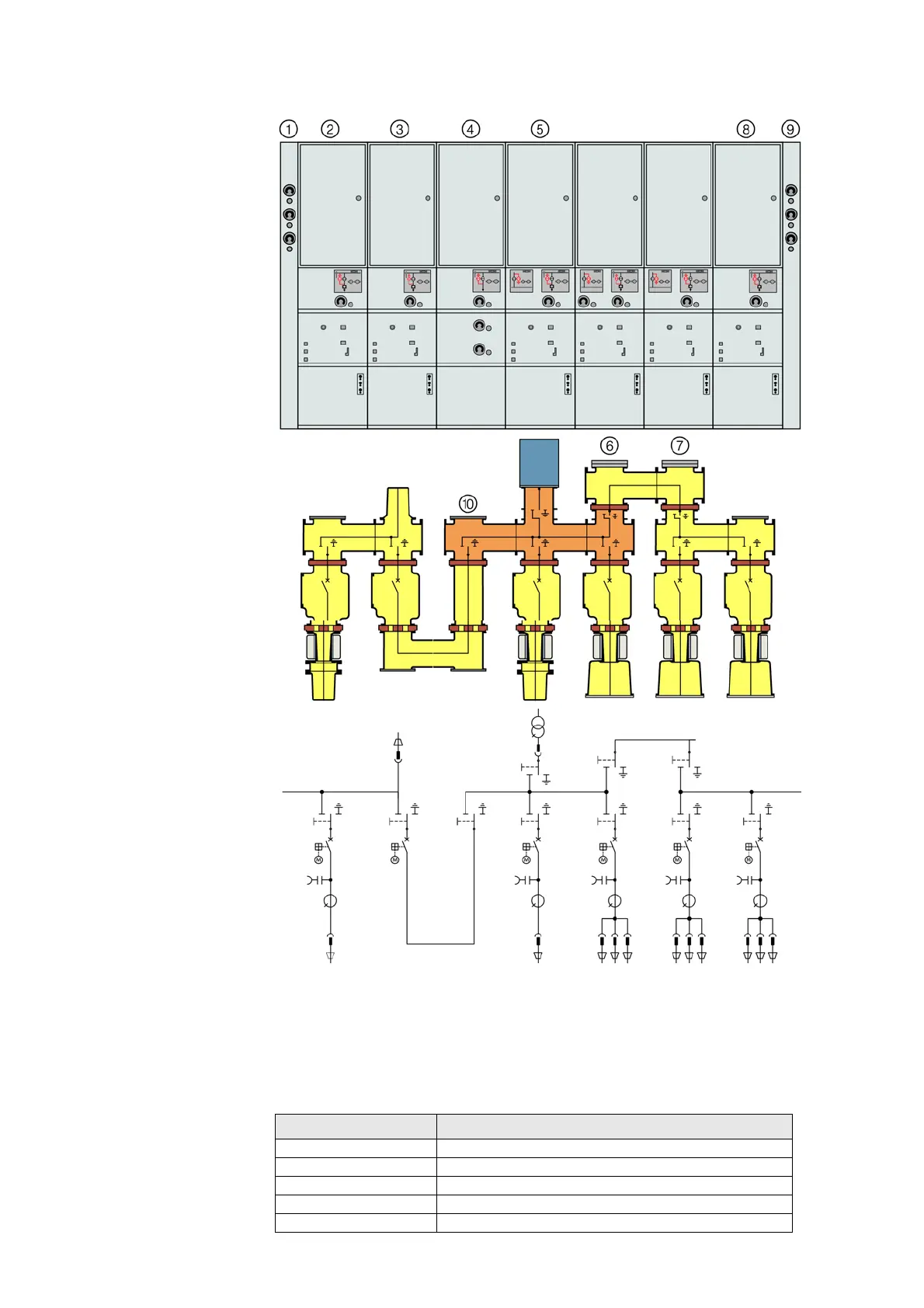
Example: Manometers at the panel
①
Switchgear termination (left)
⑥
Top-mounted bus sectionalizer (left)
②
Circuit-breaker panel
⑦
Top-mounted bus sectionalizer (right)
③
Bus sectionalizer panel with busbar connection
⑧
Circuit-breaker panel
④
Bus sectionalizer panel (bus riser)
⑨
Switchgear termination (right)
⑤
Circuit-breaker panel with disconnectable
voltage transformer on the busbar
⑩
Intermediate busbar section
Manometer designation Function
B0 Circuit-breaker, phase L1, L2, L3
B11 Busbar, phase L1
B12 Busbar, phase L2
B13 Busbar, phase L3
B15 Busbar connection / disconnectable solid-insulated connection

 Loading...


