861-9601.9 • INSTALLATION AND OPERATING INSTRUCTIONS • 8DA10 • Revision 11 197/214
Operation
39 Verification of safe isolation from supply
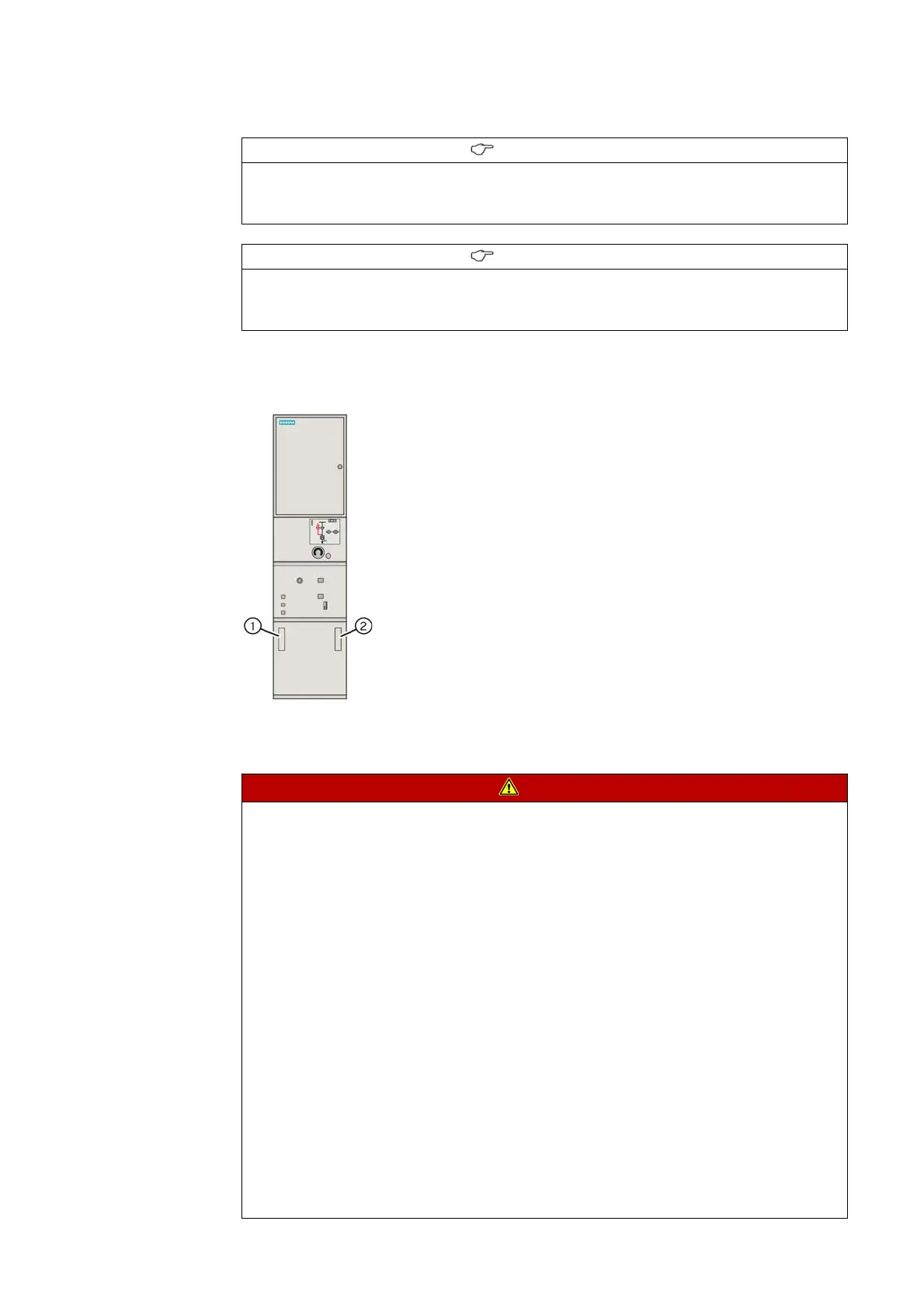
Mounting locations for voltage indicator and voltage detecting system
39.1 LRM plug-in sockets
INFORMATION
The following descriptions do not substitute reading the manufacturer documentation.
➭ Before using the voltage detecting systems, read the supplied manufacturer
documentation.
INFORMATION
The following descriptions do not substitute reading the manufacturer documentation.
➭ Before using the voltage detecting systems, read the supplied manufacturer
documentation.
Example: Circuit-breaker panel 2300 A
①
Voltage indicator /
voltage detecting system at the busbar
(option)
②
Voltage indicator /
voltage detecting system at the panel connection
(standard)
DANGER
Hazardous voltage
Will cause death, serious injury or considerable property damage.
Verify safe isolation from supply.
➭ Possible sources of failure:
- Defective voltage indicator (or device for function testing of the coupling section)
- Maloperation of the voltage indicator (or device for function testing of the coupling
section)
➭ Test the function of the voltage indicator and the coupling section in accordance with
national standards:
- On a live panel
- With a test unit according to IEC 61243-5/EN 61243-5
- On all phases
➭ Use only voltage indicators or devices according to EN 61243-5 / IEC 61243-5 /
VDE 0682-415 to test the function of the coupling section. The interface conditions have
not changed as against the old standard VDE 0681 Part 7; the corresponding indicators can
still be used.
➭ Perform repeat test of interface conditions at the capacitive interfaces, as well as on
the indicators according to the customer's specifications or national standards.
➭ Do not use short-circuiting jumpers as separate plugs. The function of the surge arrester
installed is not provided if short-circuiting jumpers are used.

 Loading...


