861-9601.9 • INSTALLATION AND OPERATING INSTRUCTIONS • 8DA10 • Revision 11 151/214
Operation
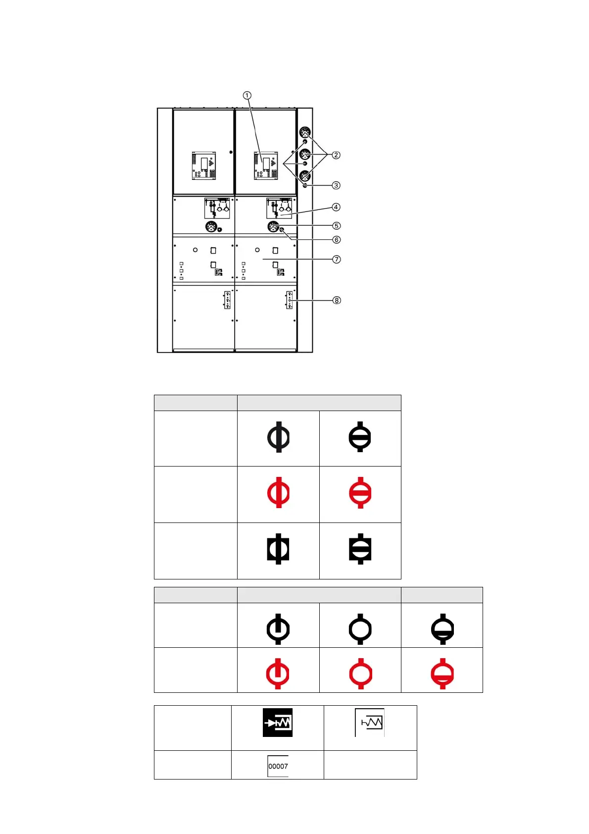
34 Control elements and indicators
Overview
Indications and
their meaning
Fig. 182: Control elements and indicators of
the circuit-breaker panel
①
SIPROTEC bay controller (option)
②
Manometer for gas compartment monitoring of
busbar gas compartments L1, L2, L3
③
Gas filling valve for busbar gas compartments
L1, L2, L3
④
Control and indication board for
three-position disconnector with
position indicator for circuit-breaker
⑤
Manometer for gas compartment monitoring of
feeder gas compartments
⑥
Gas filling valve for feeder gas compartments
⑦
Control and indication board for circuit-breaker
⑧
Sockets for LRM voltage detecting system
Switching device Indication of switch positions
Disconnector
CLOSED
OPEN
Earthing switch
READY-TO-EARTH
OPEN
Circuit-breaker
CLOSED
OPEN
Switching device Indication of faulty positions (examples)
Disconnector
Earthing switch
Closing spring
charged
not charged
Operations counter

 Loading...


