861-9601.9 • INSTALLATION AND OPERATING INSTRUCTIONS • 8DA10 • Revision 11 199/214
Operation
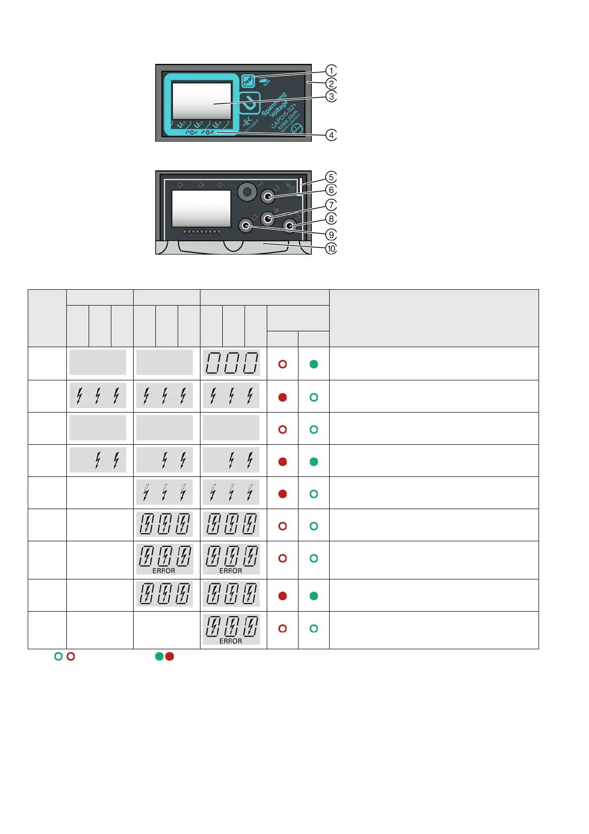
Fig. 214: CAPDIS-S2+: Cover closed
Fig. 215: CAPDIS-S2+: Cover opened
①
"Test" button
②
Cover
③
LC display
④
LEDs red and green
(state of the relay contacts)
⑤
Duct for signaling cables CAPDIS-M
⑥
Test socket L2
⑦
Earth socket
⑧
Test socket L3
⑨
Test socket L1
⑩
Short instructions
Indicatio
n
VOIS+, VOIS R+ CAPDIS-S1+ CAPDIS-S2+ Description of the indication
L1 L2 L3 L1 L2 L3 L1 L2 L3 State of the
relay contacts
1
Red Green
A0 U ≠ 0 U = 0 Operating voltage not present.
A1 U ≠ 0 U = 0 Operating voltage present.
A2 U ≠ 0 U = 0 • Operating voltage not present.
• Auxiliary voltage not available (only CAPDIS-S2+).
A3 U ≠ 0 U = 0 Failure in phase L1, operating voltage at L2 and L3
(for CAPDIS-Sx+ also earth-fault indication).
A4 - U ≠ 0 U = 0 Voltage (not operating voltage) present.
A5 - U ≠ 0 U = 0 Indication: "Test" passed (lights up shortly).
A6 - U ≠ 0 U = 0 Indication: "Test" not passed (lights up shortly).
A7 - U ≠ 0 U = 0 Overvoltage present (lights up permanently).
A8 - - U ≠ 0 U = 0 Indication: "ERROR" e.g. in case of missing auxiliary voltage.
1
LED does not light up, LED lights up
 Loading...


