Installation
96/214 Revision 11 • INSTALLATION AND OPERATING INSTRUCTIONS • 8DA10 • 861-9601.9
➭ Prepare the flanges of the busbar housings for assembly
(see page 62, "Preparing busbar assembly").
➭ Clean the sealing surfaces of the busbar housing covers with a lint-free paper, and apply
a thin film of grease.
➭ Determine the size of the desiccant bags required for each busbar housing.
➭ Place the desiccant bags in their original packing at the corresponding covers.
➭ Remove the desiccant bags from the packings.
➭ Lay the desiccant bags completely into the associated holder in the busbar housing covers.
➭ Put the busbar housing covers with the inserted bags into position. Do not jam any parts of
the desiccant bags in the sealing surfaces; otherwise, there will be leaks.
➭ Fasten the busbar housing covers crosswise. Tightening torque: 20 Nm.
Evacuating the busbar run
with the vacuum pump
Before filling with SF
6
gas, the air must be removed from the busbar run to be filled with gas
(evacuation). One of the covers next to the right and left end panel of the switchgear contains
the manometers and gas filling valves for one busbar run.
Evacuating a five-panel busbar run takes about 30 to 40 minutes.
➭ Undo the locking cap of the gas filling valve ③ from the closed busbar run.
➭ Connect the vacuum pump to the valve of the busbar run. Use short tubes with the largest
inside diameter possible.
➭ Evacuate the housings down to a pressure of less than 2 kPa.
Manometer indication: -100 kPa. Measure the pressure with the vacuum pump locked.
➭ Depending on the inside diameter and length of the vacuum pump tube, let the pump
operate for another 5 to 15 minutes.
➭ Remove the vacuum pump tube. The gas filling valve closes automatically.
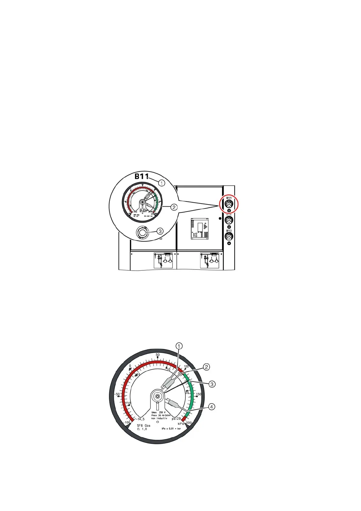
Fig. 108: Manometer and gas filling valve at
the switchgear front
①
Designation for the busbar run
②
Manometer
③
Gas filling valve
Fig. 109: Detail view of manometer
①
Signaling contact:
Pressure lower than minimum functional level
②
Signaling contact:
Minimum functional level
③
Gas pressure indicator:
Rated functional level 120 kPa
④
Signaling contact:
Maximum functional level 180 kPa
The data in kPa are values at
20 °C ambient air temperature

 Loading...


