20
AOP Operating Instructions – Issue 07/05
6SE6400-5AP00-0BB0
4.1.3 Drive Type Check
The AOP will check the type of inverter to which is connected. If the drive type is
incompatible with the AOP, it will refuse to function and return the user to the
Main Menu.
4.2 Operating in Master Mode
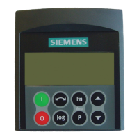
Selecting ‘Operate’ from the Main Menu with Master mode configured produces
an operation screen display as shown below:
A slave inverter is selected by using the
and keys.
Up to 30 inverters can be connected and controlled by one AOP.
A two-digit number on the left-hand side of the display identifies each inverter.
In the top left-hand on the screen an icon is displayed indicating the current
status of the inverters operation. A list of all the icons is shown below.
To configure inverters for network operation, the following parameters should be
set to the indicated values:
P0700 = 5
P2014.0 = 5000
P2011.0 = Unique number for each drive on the network.
For more information on setting inverter for network operation, see Section 2.2
above.
Button Function
Indicates the inverter is active and communicating.
Indicates no active slave (icon is blank).
F
Indicates an inverter fault has been recorded and the
inverter has tripped.
A
Indicates an inverter with active warnings.
Indicates an inverter with communications problems.
ρ
Indicates a non-MM4 inverter (possibly MM3) -
parameter upload only.
4.2.1 Broadcast Operations
Warning
Parameter P2011=31 cannot be selected using the AOP. If P2011=31
is selected using software such as DriveMonitor or STARTER, the
inverter will enter Broadcast Mode and will not respond to any
commands from the AOP. In Broadcast Mode the inverter will only
respond to broadcast messages.
The purpose of the broadcast function is to allow all connected inverters to be
controlled simultaneously.
With the broadcast function selected it is possible to perform the following
functions on all connected inverters:
 Loading...

