Siemens AG SPR2-320.814.02.01.02 ARCADIS Orbic
01.05 CS SD 24
3D Reconstruction Upgrade Part 1 25
Page 25 of 46
Medical Solutions
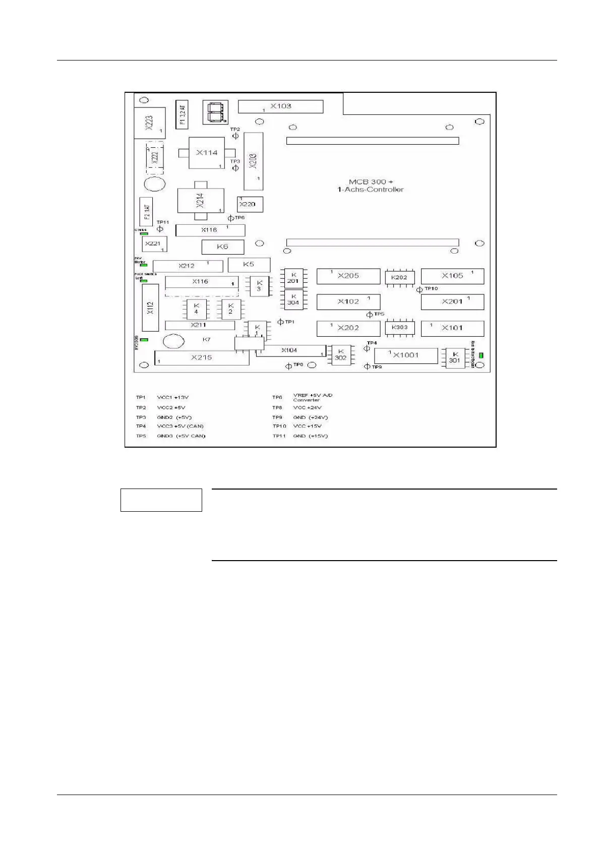
Fig. 17: Connectors D200
NOTE
Cable ties or shielding can be removed as required during instal-
lation.
After successful installation, the shielding must be reestablished
and the cables secured with the cable ties.
• (Fig. 17 / p. 25) shows the layout of board D200.
• Disconnect plug D1.X3 from PC board D1. Connect the plug to connector D200.X103
on interface PC board D200. Ensure proper locking.
• On D30, reconnect plug D30.X5 to D200.X115 on interface PC board D200. For this
purpose, slip the cable out of the existing shielding and reinsert it from the opposite
side.
• On D30, reconnect plug D30.X12 to D200.X112 on interface PC board D200. For this
purpose, slip the cable out of the existing shielding and reconnect it to the shielding at
D200 (interface) (Fig. 18 / p. 27). Retighten the shielding on PC board D30.
Cable no. 3, item number n.a. 0
• Connect plug D30.X5 on D30 and plug-in location D200.X215 on D200.

 Loading...