Operating Manual - Elevator Door Operation AT18
37
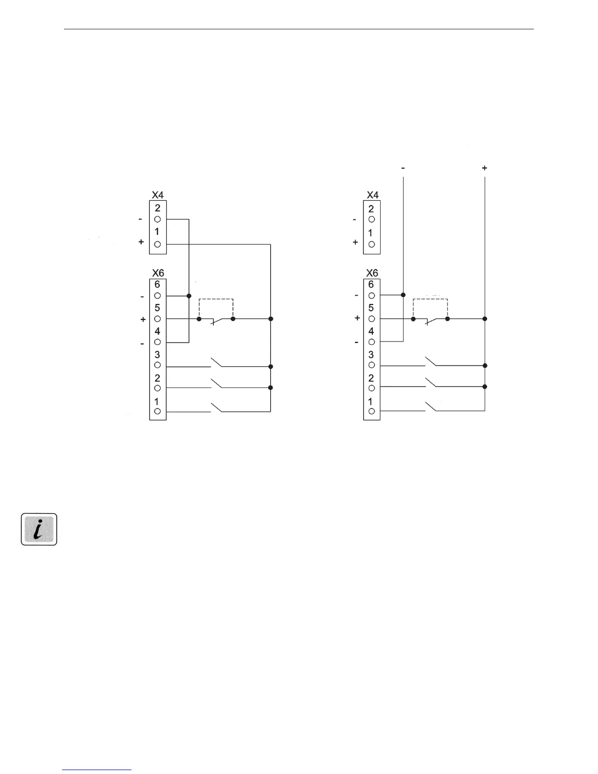
15.8 Attachment 8: Control inputs terminal circuit diagram
Connection with internal 24V supply Connection with external supply
Illustration 9
Nudge = switch on CLOSE and nudge instruction at the same time (only effective in closing
direction).
NOTICE
The 4V current outlet X4 may not be connected to a foreign (external) current facility (e.g. elevator
controls of a higher order).
A connection from X4 connection (minus 4V) against PE is possible.
From the
elevator control
+10V up to +28V DC
9mA up to 27mA
per inlet
Light barrier
or bridge
Power outlet
24V / 0.4A
Nudge
Close
Open
Nudge
Close
Open
Light barrier
Nudge
Close
Open
Light barrier
or bridge
Nudge
Close
Open
Light barrier
Power outlet
24V / 0.4A



 To Next Page